5-50
CHAPTER 5 Periodic Inspection
8) Remove the wave generator from the motor shaft. The wave generator is
secured with an M4 set screws. (See Fig. 5-45.)
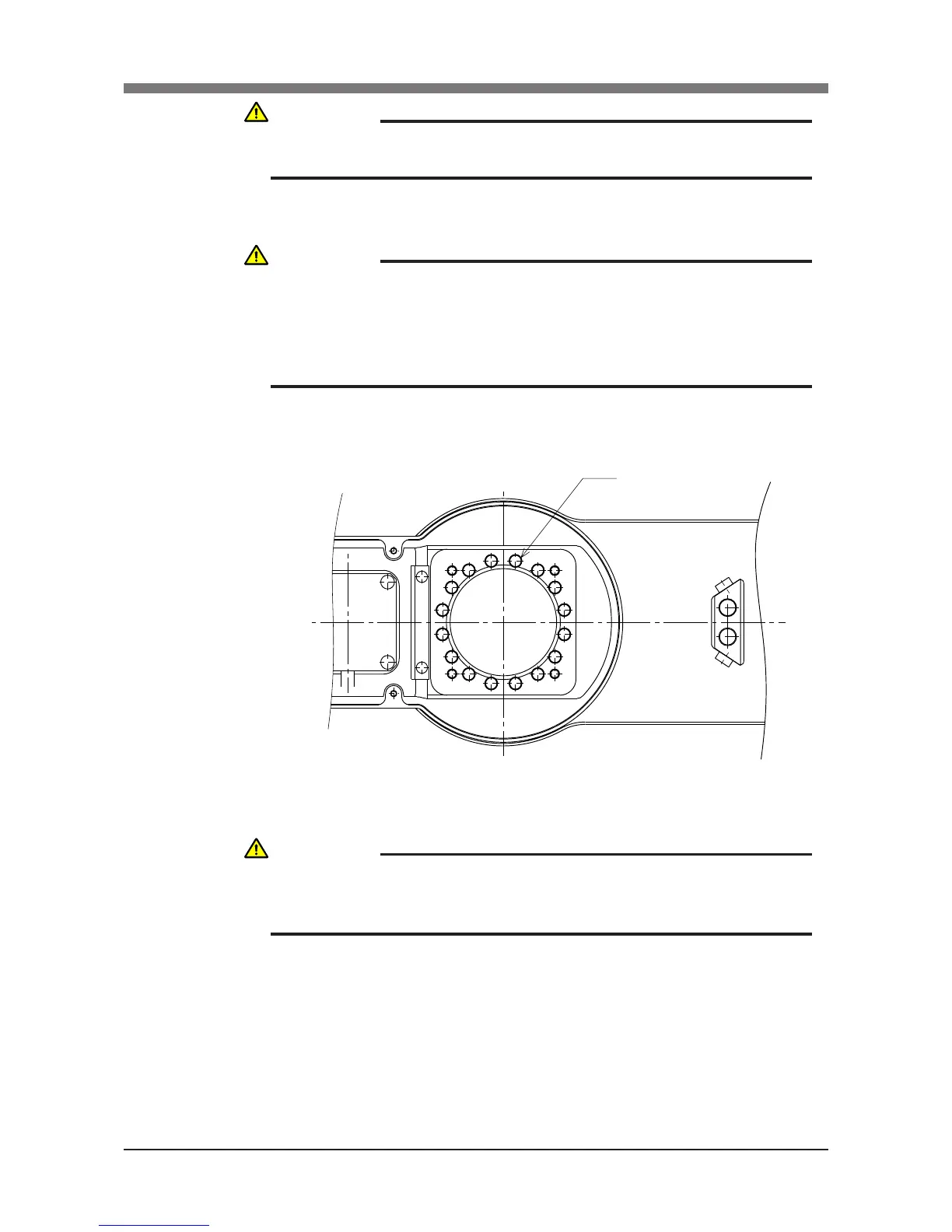
9) Remove the Y-axis arm installation bolts (M4×20L, 16 pieces).
(See Fig. 5-42.)
Fig. 5-42
10) Remove the Y-axis arm and place it where it will not obstruct the work.
CAUTION
AN O-RING IS FITTED TO THE MOTOR, SO BE CAREFUL NOT TO LET IT
DROP INTO THE PERIPHERAL UNIT.
CAUTION
WHEN YOU REMOVE THE Y-AXIS ARM INSTALLATION BOLTS (M4×20L,
16 PIECES) IN THE NEXT STEP, THE Y-AXIS ARM MAY COME OFF
CAUSING A HAZARDOUS SITUATION. BE ESPECIALLY CAREFUL TO
KEEP THE ARM FROM FALLING WHEN A HEAVY TOOL IS ATTACHED
TO THE ARM TIP.
CAUTION
AN O-RING IS FITTED TO THE UPPER SURFACE OF THE HARMONIC
DRIVE, SO BE CAREFUL NOT TO LET IT DROP INTO THE PERIPHERAL
UNIT.
 Loading...


