5-51
CHAPTER 5 Periodic Inspection
11) Remove the Y-axis harmonic drive installation bolts (M4×45L, 8 pieces).
(See Fig. 5-43.)
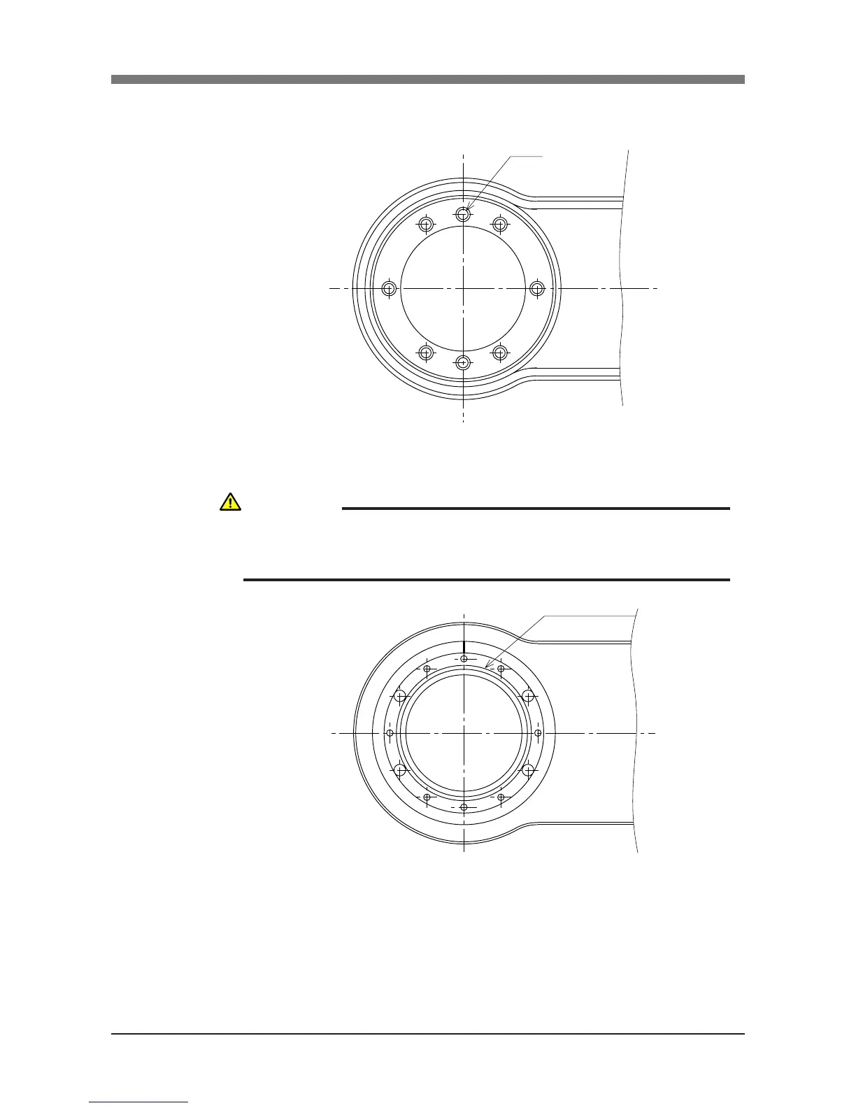
Fig. 5-44
13) Fit a new O-ring coated with harmonic grease into the O-ring groove on the
X-axis arm. (See Fig. 5-44.)
14) Place the new harmonic drive on the X-axis arm, and secure it with the
bolts (M4×45L, 8 pieces) you removed earlier. Apply small amounts of
“Screw Lock” to the bolts and tighten them uniformly to secure the
harmonic drive from the backside. (See Fig. 5-43.)
CAUTION
AN O-RING IS FITTED TO THE UPPER SURFACE OF THE X-AXIS, SO BE
CAREFUL NOT TO LET IT DROP INTO THE PERIPHERAL UNIT. (SEE FIG.
5-44.)
 Loading...


