'
Bit DescriptionName
5 Multi-function output 2 This function is set in n10.
6 Status output 0: Inoperable 1: Operable
7 Error status 0: Abnormal 1: Normal
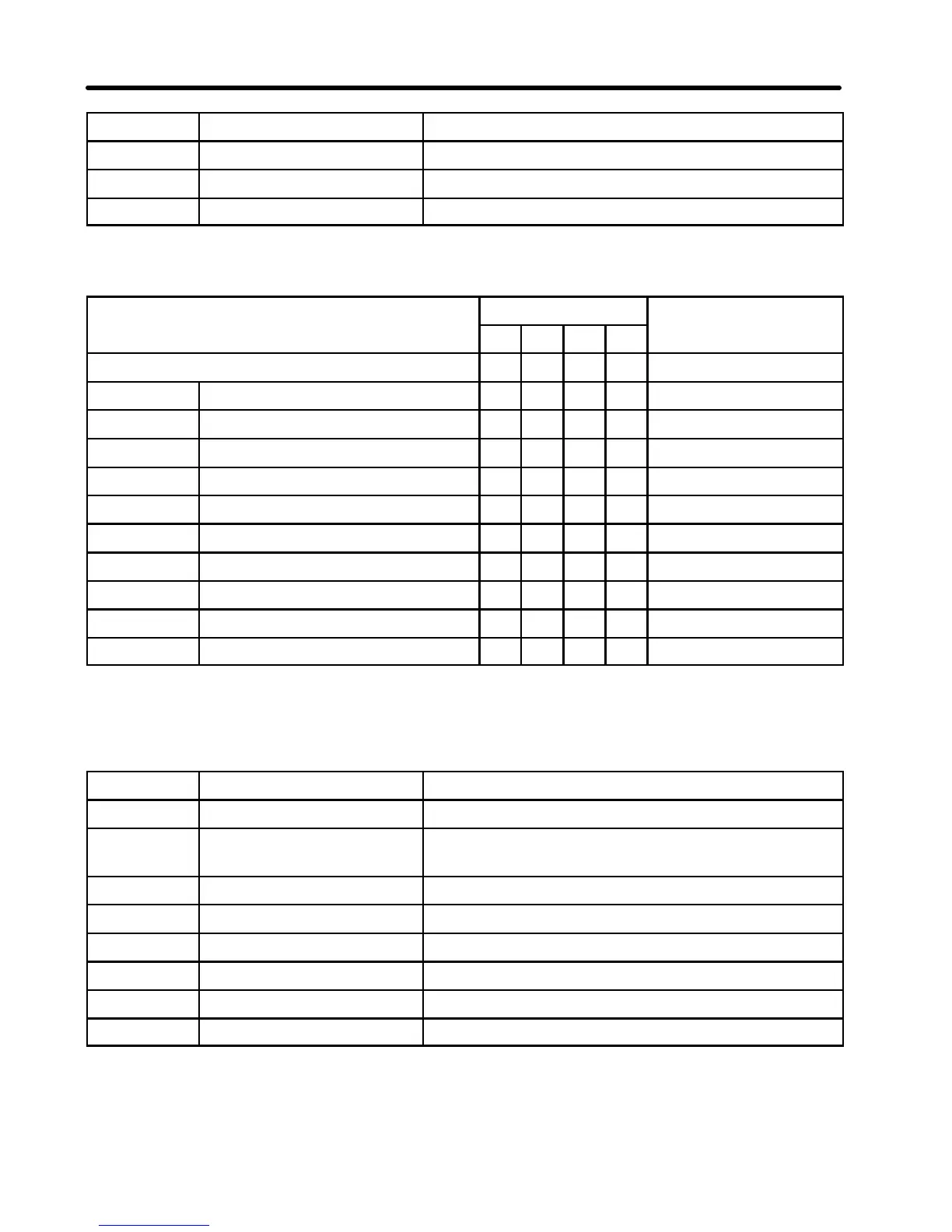
Error Code Table
Error type Bit Error code
3 2 1 0
(hexadecimal)
(No error) 0 0 0 0 0
OC Overcurrent 0 0 0 1 1
OV Main circuit overvoltage 0 0 1 0 2
OL2 Inverter overload 0 0 1 1 3
OH Radiation fin overheated 0 1 0 0 4
EF1to3 External fault 1 0 0 0 8
F00to06 Inverter fault 1 0 0 1 9
OL1 Motor overload 1 0 1 0 A
OL3 Over-torque 1 0 1 1 B
UV1 Main circuit undervoltage 1 1 0 0 C
UV2 Control power supply fault 1 1 0 1 D
Transmission Data Input (from PC to Inverter)
Word n+1
Bit Name Description
0 Run command 0: Stop 1: Run (fixed function)
1 Reverse rotation com-
mand
0: Forward 1: Reverse (fixed function)
2 (Unused) (Input will be ignored)
3 Fault reset 1: Fault reset
4 Multi-function input 1 This function is set in n06.
5 Multi-function input 2 This function is set in n07.
6 Multi-function input 3 This function is set in n08.
7 Auxiliary input Available when 0 is set in n06
Chapter 4