(
Setting Override Data
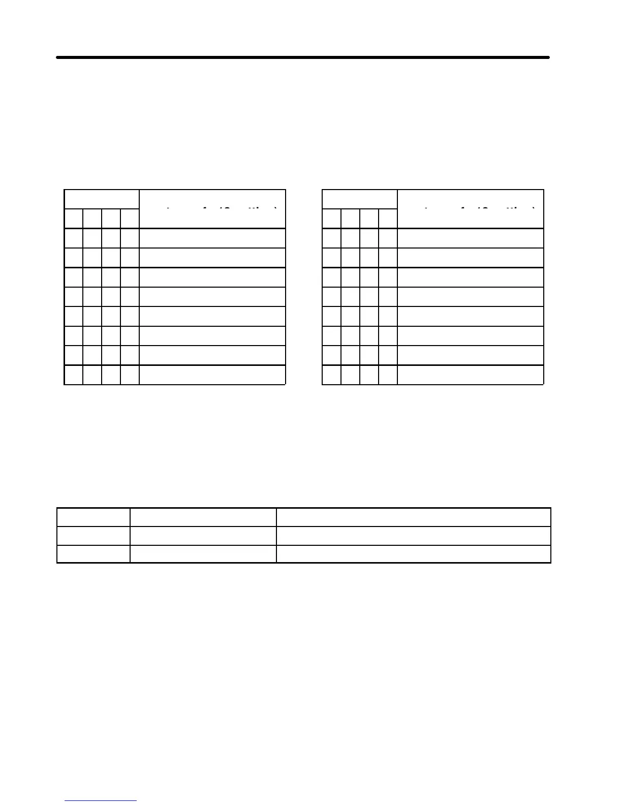
•If 0 is set in n06 (multi-function input selection 1), bits 4 to 7 are used to set override
data.
•Output frequency can be set in terms of the percentage of the value set in n18 (fre-
quency reference 8).
Bit
Override value (per-
Bit
Override value (per-
7 6 5 4
centage of n18 setting)
7 6 5 4
centage of n18 setting)
0 0 0 0 0 (%) 1 0 0 0 80 (%)
0 0 0 1 10 (%) 1 0 0 1 90(%)
0 0 1 0 20 (%) 1 0 1 0 100 (%)
0 0 1 1 30 (%) 1 0 1 1 110 (%)
0 1 0 0 40 (%) 1 1 0 0 120 (%)
0 1 0 1 50 (%) 1 1 0 1 130 (%)
0 1 1 0 60 (%) 1 1 1 0 140 (%)
0 1 1 1 70 (%) 1 1 1 1 150 (%)
Up/Down command
•If 15 is set in n08 (multi-function input selection 3), bits 5 and 6 are used as the up and
down commands, respectively.
•When the signal is ON, the output frequency is increased or decreased.
Bit Name Description
5 Up command Increases the output frequency when ON
6 Down command Decreases the output frequency when ON
•When these bits are simultaneously turned on, the output frequency remains un-
changed.
Chapter 4

 Loading...


