9
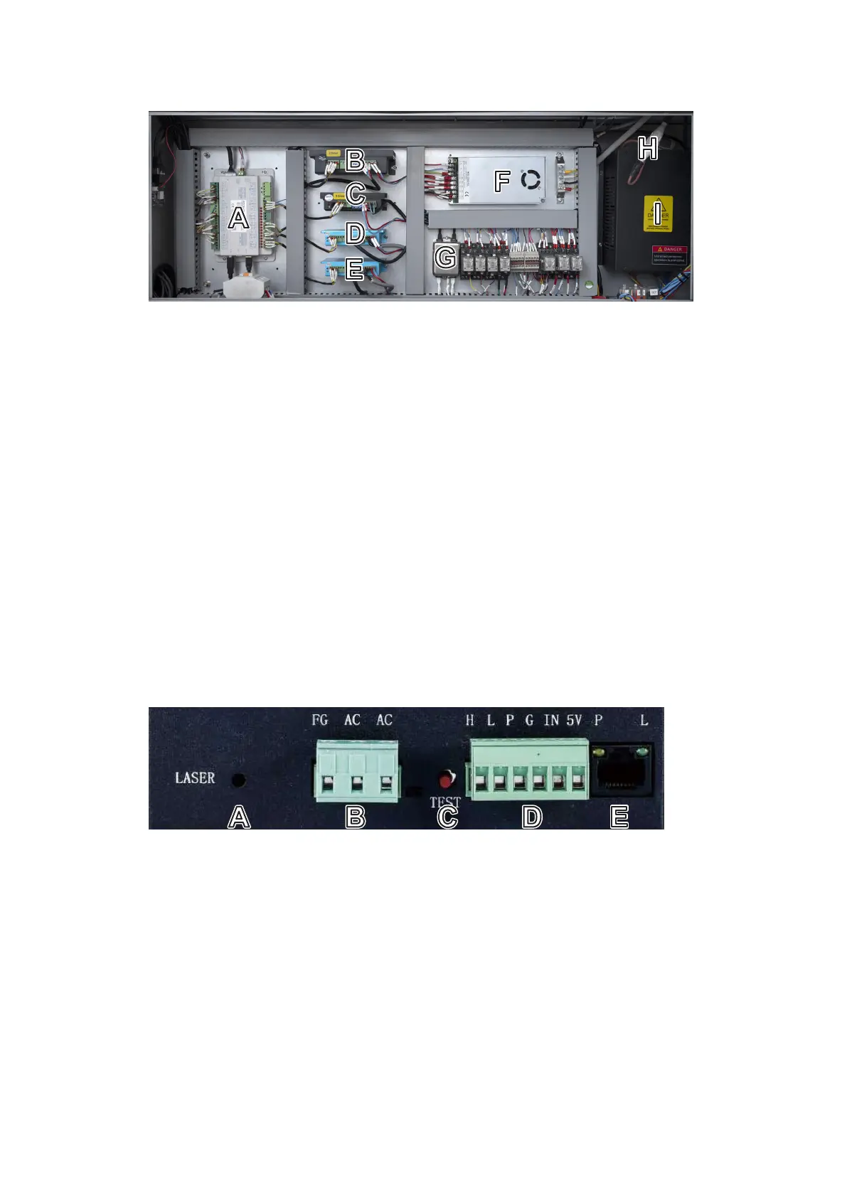
1.5.6 Electronics Bay
A. Mainboard—This circuit board controls the engraving process, responding to commands from your engraving
software or the machine’s control panel.
B. Z-Axis Driver—This device controls the motor that raises and lowers the workbed.
C. Rotary-Axis Driver—This device directs attached and enabled rotary devices.
D. Y-Axis Driver—This device powers the motor that moves the laser head along the Y-axis rail.
E. X-Axis Driver— This device powers the motor that moves the laser head along the X-axis rail.
F. Control Power Supply—This device powers the machine’s control panel and mainboard.
G. EMI Filter—This device helps protect the sensitive electronics in the mainboard from interference from the
power supply.
H. Anode Connection—During replacement of the tube or power supply, use this socket to more easily and safely
restore the high-voltage connection between the two.
I. Laser Power Supply—This device transforms standard electricity into the extremely high voltage necessary for
the laser tube.
A. Laser Signal Indicator—This light shows when current is being sent to the laser tube.
B. Main Power Terminal—This terminal block holds the power supply’s connection to the engraver’s grounding
(FG) and to the main power supply (AC).
C. Test Button—This button is used to attempt to test re the laser when troubleshooting problems. (Remember to
place a piece of laserable scrap material on the workbed before any such test ring.) If the laser res successfully,
the problem will usually be with the control panel or its connections.
D. Connection Terminal—This terminal block ensures that the water sensor, interlocks, etc. (P) can turn o the
laser immediately in the case of an emergency, as well as oering active high (H) or low-voltage ring (L),
potentiometer inputs (IN), a 5V DC power connection (5V), and a pin for return lines (G).
E. Ethernet Connection—This can be used for connecting testing devices while troubleshooting electrical issues.
Its indicator lights show its connection to power (P) and the active laser (L).