18
3.7 Main Power Connections
Conrm that the labeling beside the connection sockets matches your power supply. If you have not already done so,
connect one end of the power cables to the connection sockets and the other ends to grounded outlets. The combined
electrical load of all the major components of this device will draw over 30A. If you have not prepared a robust
dedicated line, keep the engraver and chiller on separate 20A circuits. The external fan can be plugged into the
engraver or use the same circuit as the chiller, but using a separate 15A or 20A circuit is recommended. Under NO
circumstances should you switch on the devices if the voltages do not correspond or if your circuits will be unable
to handle the necessary load.
Fluctuation along the lines should be less than 5%. If this is exceeded, the engravers’ own fuses will blow to protect
its internal electronics. They are located below the connection sockets and are accessible from the exterior. Do not
connect this device to standard extension cords, power strips, or surge protectors.
3.8 Control Computer
See the software manual for details on the requirements for the control computer. The control computer can be
connected directly using the provided USB cable or through Wi-Fi. If the control computer is directly connected to
the engraver, it should not be placed more than 15 feet (4.5 m) away to avoid possible interference to the signal on its
line. A Windows-compatible copy of RDworks V8 is provided on the USB ash drive that came with your engraver.
Familiarize yourself with the software’s image design features and laser control settings before using it to operate
the laser.
When you rst congure your software to work with the laser, the device name to search for will be the mainboard
model: RDC6445GT5. Make sure that you set the software to use an X axis length of 1000mm and a Y axis length
of 600 mm. The default origin position will be at the workbed’s top left corner. If you change this in your software,
be sure to also change the control panel settings to match. (See §4.4 below for details on this and Setting Engraver
IP Addresses for connecting to the engraver within a LAN or over the internet.)
3.8.1 RDWorks V8 Reverse Compensation
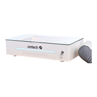
2. Click open the le and click “Install”. Choose a
le route that you deem suitable.
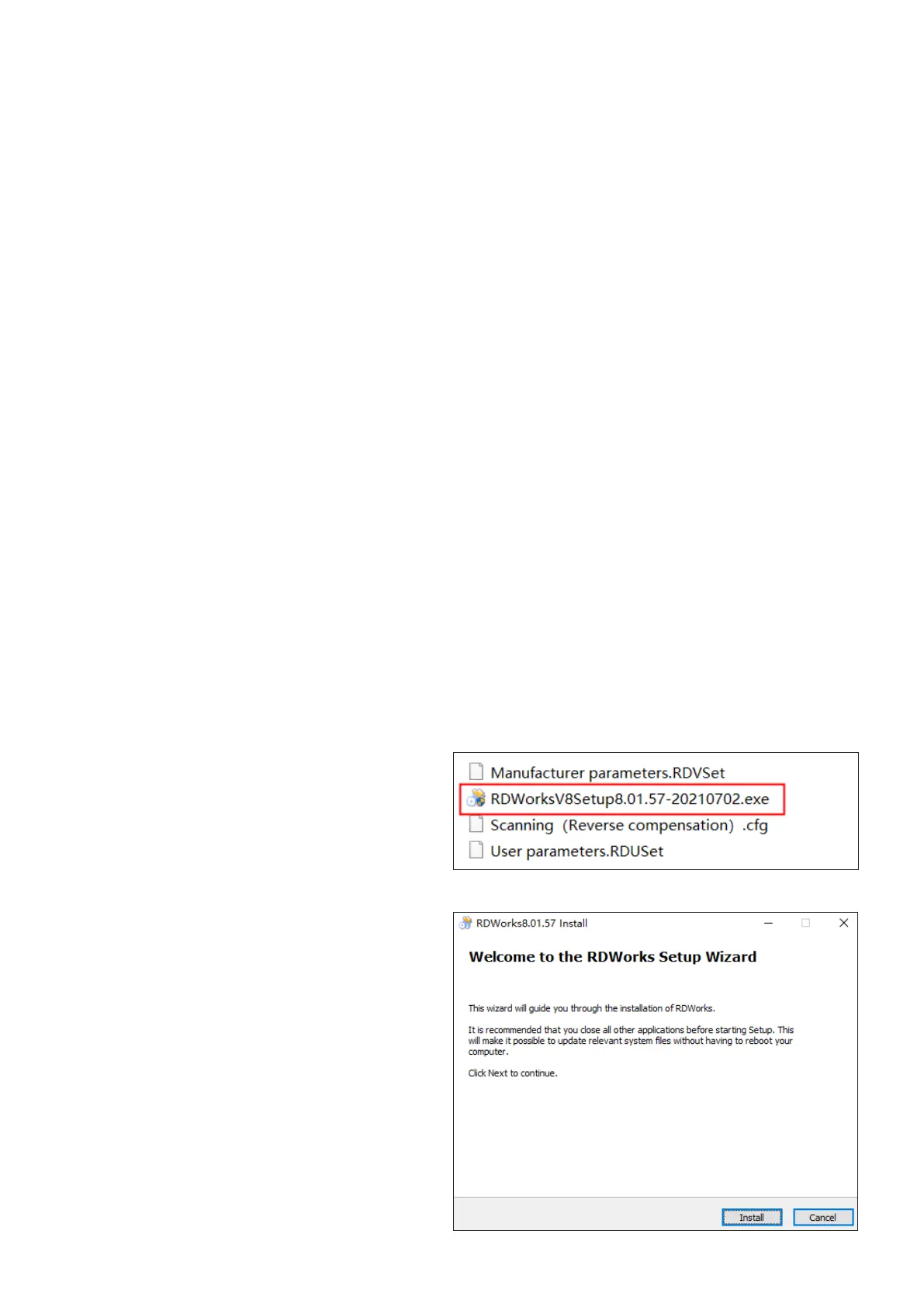
1. Insert the provided USB ash drive into a port
on your control laptop. Find the le as shown.
RDWorksV8Setup8.01.57