69
6.6 Parts Replacement
This engraver should not be modied or disassembled by anyone except trained and licensed professionals, but
some consumable parts may require replacement after prolonged use. Contact your vendor or our technicians if you
have any questions about tment or installation. Using incompatible components is highly dangerous and waives all
the manufacturer’s liability for any damage or injury caused.
ALWAYS completely disconnect the engraver from its power supply before replacing any parts.
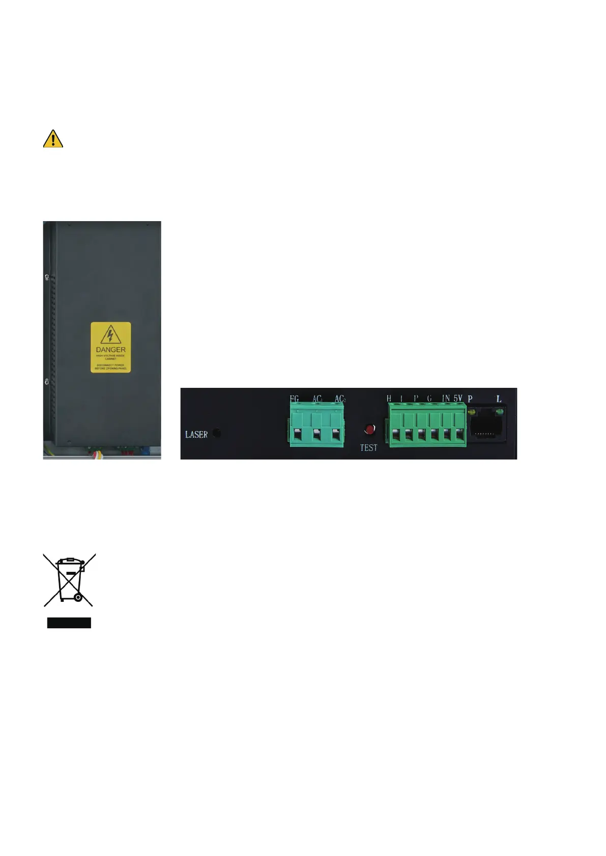
Take special care when replacing the laser tube or its power supply, as both have extremely high voltage
connections. If you replace the power supply with an identical model, you will be able to use the same screw
terminal blocks as a unit. If you change to a dierent power supply, refer to the following diagram to move the
wires to the correct placement on the new unit. The high-voltage anode wire should be
6.7 Disposal Instructions
Electrical products should not be disposed of with household products. In the EU and UK, according
to the European Directive 2012/19/EU for the disposal of electrical and electronic equipment and its
implementation in national laws, used electrical products must be collected separately and disposed
of at the collection points provided for this purpose. Locations in Australia, Canada, and the United
States may have similar regulations. This engraver’s R-410A refrigerant also requires special
handling for reuse or legal disposal. Contact your local authorities or dealer for advice.
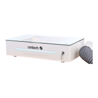
FG: Main ground connection
AC1: Neutral wire to the main power connection
AC2: Live wire to the main power connection
H: Live wire to receive active high-voltage ring commands
L: Live wire to receive active low-voltage ring commands
P: Live wire(s) to the water sensor etc.
G: Neutral wire(s) to the water sensor, PWM level shifters, etc.
IN: Live wire(s) to receive PWM and other power adjustment commands
5V: 5V DC connection(s) to power PWM level shifters, potentiometers, etc.