61
It is recommended that you use your engraver in a climate-controlled area with a set target temperature. If using your
engraver in other conditions is unavoidable, use laser-safe antifreeze.
When using your engraver in areas below standard room temperature, you can reduce needless heating and chilling
by switching the control mode (F3) to “intelligent”. This will use the chiller’s ambient temperature sensor to keep
your water at set dierence from the room temperature. The default dierence is −3°C with a tolerance of ±2°C. For
example, if your engraver has been left idle in a room that is 15°C (60°F), the chiller will normally begin work by rst
heating the water to 25°C and then stop work when it reaches 39.5–40.5°C. In intelligent mode, it will begin work
by chilling the water to 10–14°C and stop work when it reaches 18–22°C. This last number can be changed using
the High Temp. Alarm (F4). If it is possible the room will warm noticeably during the day or because of the laser,
reduce the ultrahigh temperature alarm (F6) from 45°C to 40°C or lower to prevent your laser’s components from
overheating and excessive wear.
Before using the intelligent mode, check the “t1” readings before and after normal use. This will help you
adjust for the sensor’s own readings against the temperature in other parts of your work area.
The device address should not be changed. If it ever accidentally is reset, return it to its default setting of “1”. To
remove all changes and restore all factory default settings, wait at least 30 seconds after the chiller has been turned
on and then hold ⯅ and ⯆ simultaneously until the display reads “rE” and then automatically resets.
If any alarms activate after all air has been cleared from the lines during initial setup (§3.5), nd the specic error
code in §6.6 below and make the necessary adjustments to handle it.
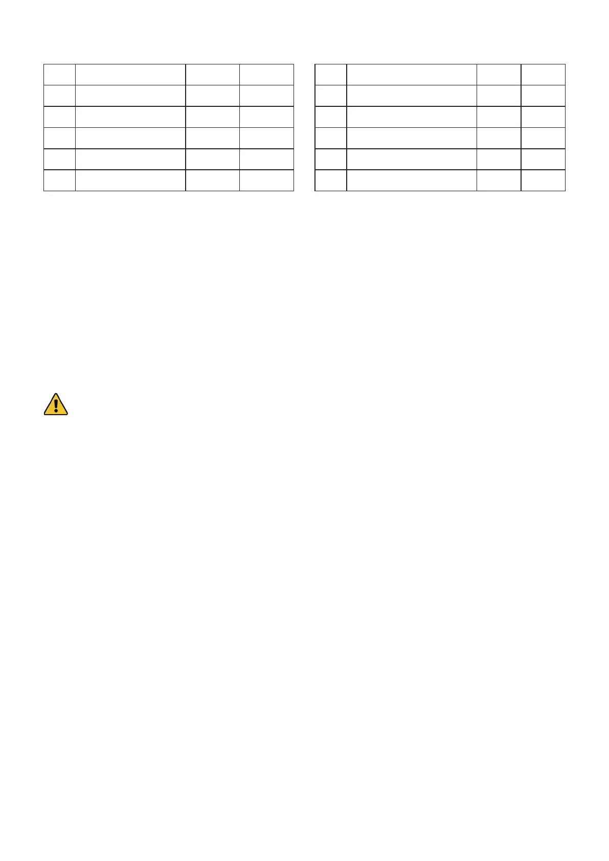
F0 Target Temp. 25°C N/A
F1 Temp. Dierence N/A −3°C
F2 Temp. Tolerance ±0.5°C ±2°C
F3 Control Mode 0 1
F4 High Temp. Alarm +15°C +5°C
F5 Low Temp. Alarm −15°C −10°C
F6 Ultrahigh Temp. Alarm 45 45°C
F7 Access Passcode 8 8
F8 Upper Temp. Limit 31°C +30°C
F9 Lower Temp. Limit 25°C −5°C
F10 Low Flow Alarm (dL/min) 0.5 0.5
F11 Device Address 1 1