1500 North Belcher Road, Clearwater, FL 33765 • Tel (727) 447-6140 • Fax (727) 442-5699 • sales@onicon.com
D-100 Flow Display Manual 08-12 - 0634-7 Page 17
3.3.2 Average Frequency (Pulse) Flow Input
The D-100 is provided with a separate input for frequency or scaled pulse ow signals,
(terminals 6 and 7). This input can be congured to accept an active, positive going pulse
(5-24VDC)outputsignal,anopencollectoroutputsignaloracontactclosure(drycontact)
output. The maximum input frequency is 500 Hz. Contact ONICON for technical
assistance in conguring and programming this input.
3.3.3 Analog Input (Flow)
The D-100 is provided with a separate input for analog
ow signals (T4 terminals 4 and 5). This input can be
congured to accept active or passive (loop powered)
4-20 mA signals. Contact ONICON for technical
assistance in conguring and programming this input.
3.3.4 Directional Contacts
The D-100 is provided with a separate input for
determining ow direction. Connections for this input
are made at T4 terminals 8 (+) and 9 (-). This input can
be connected to a non-polarized contact closure relay or
an open connector output. Note that the input is
polarized for sinking (NPN) open collector outputs.
Totals will accumulate in the mode 1 registers whenever
the contacts are closed.
3.3.5 Auxiliary Rate Inputs
The D-100 can be provided with two optional analog rate
inputs capable of powering any standard 4-20mA loop
powered sensor. The inputs can also be congured from
the factory to accept an active (powered) 4-20mA signal.
Rate data from the two sensors is available via the
network interface and the analog 4-20mA signals can be
replicated via the optional multi-analog output board.
Rate data from the auxiliary analog inputs cannot be
viewed on the local display. Analog input Ai3 is
connected to T3 terminals 1 (+) and 2 (-). Analog input
Ai4 is connected to T3 terminals 3 (+) and 4 (-). Do not
exceed 4.5 in-lb (0.5 Nm) of torque,
when tightening the terminals.
3.3.6 Auxiliary Pulse Input
The D-100 can be provided with an optional auxiliary pulse input. This option is only
available on displays with serial connections. It allows the D-100 to receive a pulse input
from an external device such as a power meter or gas meter. The pulses are totalized in an
internal register and are available via the serial communications network. This register can
be zeroed on demand via the network. Contact ONICON for more information.
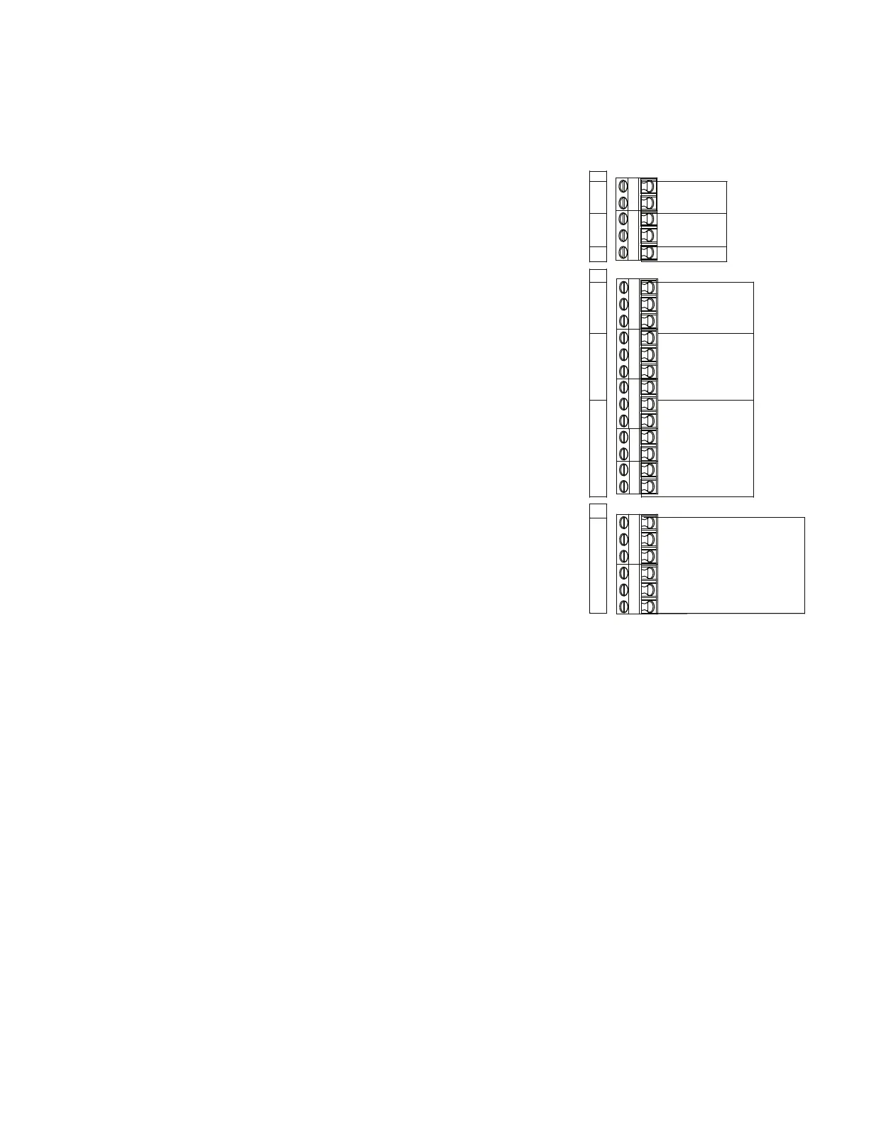
T3
1
2
3
4
5
T4
1
2
3
4
5
6
7
8
9
10
11
12
13
T5
1
2
3
4
5
6
AUX RATE INPUTS
SIGNAL
REFERENCE
SIGNAL
REFERENCE
SHIELDS
24 VCD SUPPLY +
SUPPLY COMMON -
SHIELD
4-20 mA +
4-20 mA -
FREQUENCY +
FREQUENCY -
DIRECTION +
DIRECTION -
ALARM +
ALARM -
TOP TURBINE
BOTTOM TURBINE
4-20 mA +
0-10 VDC +
ANALOG COMMON -
ISOLATED ANALOG COMMON -
SCALED +
SCALED -
FLOW METER INPUTS
AUXILIARY FLOW METER SIGNALS
Ai4
Ai3