1500 North Belcher Road, Clearwater, FL 33765 • Tel (727) 447-6140 • Fax (727) 442-5699 • sales@onicon.com
D-100 Flow Display Manual 08/12 - 0634-7 Page 10
1
H1
D3
D4
TB1
1/4 AMP
NEUTRAL
F1
120VAC
VAR1
D1
D2
T1
LED1
20075-50 REV. A
R1
H3
10
G
G
J2-12
+24
+15
J2-1
1
60HZ
G
5
ONICON INC.
20036 Rev. D
H2
1
5
10
15
20
25
30
35
40
45
H3
1
5
10
15
20
25
30
35
40
45
S1
RUN
TEST
60 HZ
LED1
FLOW
INDICATOR
C1
C2
C3
U1
J1
R3
R5
R1
C4
U2
C6
D6
D5
C5
R7
AUXILIARY FLOW METER SIGNALS
4-20mA -
0-10 VDC +
ANALOG COMMON -
ISOLATED ANALOG COMMON -
SCALED +
SCALED -
24 VDC SUPPLY +
SUPPLY COMMON -
SHIELD
4-20mA +
4-20mA -
FREQUENCY +
FREQUENCY -
DIRECTION +
DIRECTION -
ALARM +
ALARM -
TOP TURBINE
BOTTOM TURBINE
FLOW METER INPUTS
SIGNAL
REFERENCE
SIGNAL
REFERENCE
SHIELDS
Ai3Ai4
AUX RATE INPUTS
T3
1
2
3
4
5
T4
1
2
3
4
5
6
7
8
9
10
11
12
13
T5
1
2
3
4
5
6
15 V PULSE
+ -
OUTPUTS
TOTALIZER OUTPUT
MODE 1
TOTALIZER OUTPUT
MODE 2
MODE STATUS
CHANNEL A
ANNALOG OUTPUT
CHANNEL B
ANALOG OUTPUT
CHANNEL C
ANALOG OUTPUT
CHANNEL D
ANALOG OUTPUT
ALARM
OUTPUT
+
-
+
-
+
-
+
-
T1
1
2
3
4
5
6
7
8
9
10
11
12
13
14
15
16
17
18
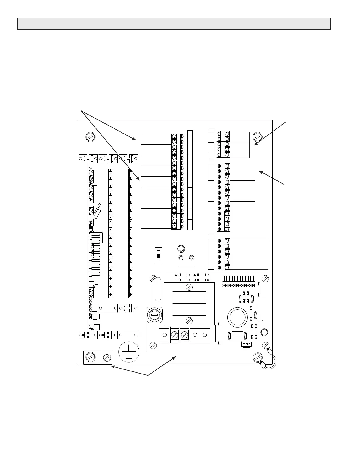
Pulse and analog output connections
Input power & earth connections
Flow meter
connections
Auxiliary analog
input connections
3.3 ELECTRICAL INSTALLATION
The electrical installation of this product must comply with all federal, state and local building
codes. Connect and re-verify all input, output, network interface and safety earth wiring
connections prior to connecting power.
The drawing below shows where signal, power and earth connections are made on the mother
board located inside the D-100 enclosure. Network and auxiliary pulse input connections are
made on the network interface board (not shown). Refer to section 3.3.1 for detailed information
on connecting ow meters, sensors, output signal and power connections.
3.3.1 Input Signal Connections from Flow Meter
Make connections on the mother board, located inside the enclosure, at terminal strips T3
and T4. Do not exceed 4.5 in-lb (0.5 Nm) of torque when tightening.