1500 North Belcher Road, Clearwater, FL 33765 • Tel (727) 447-6140 • Fax (727) 442-5699 • sales@onicon.com
D-100 Flow Display Manual 08-12 - 0634-7 Page 23
4.6 COMMISSIONING
Upon initial installation, it is strongly recommended that both the D-100 and its associated ow
meter be commissioned to ensure that they are properly installed and functioning correctly.
This process involves verifying the mechanical installation, measuring ow signals and then
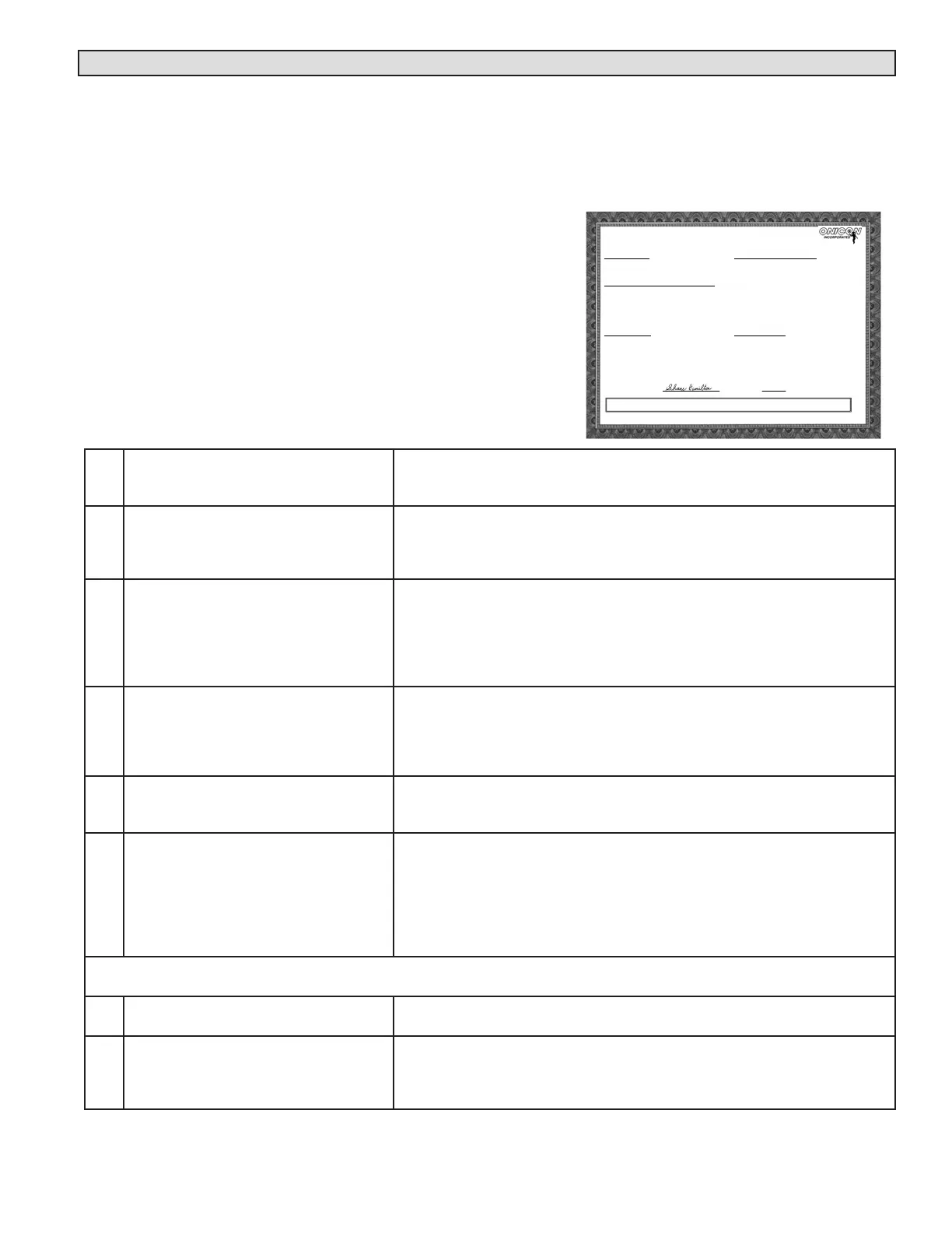
comparing these measurements to the specied installation and operating parameters listed on
the certicate of calibration provided with the display. The data collected during this initial
commissioning process will then serve as baseline data for periodic revalidation of the meter
operation.
COMMISSIONING PROCEDURE
Please read all installation instructions carefully before
proceeding. Wiring diagrams are located in this manual.
Use the display Certicate of Calibration to verify that
the specied installation & operating parameters match
the actual conditions at the location where the display
is installed. A worksheet for checking these steps and
recording measured values is located on the following
page.
1. Conrm that the D-100 is being
installed with the correct ow meter
and any optional sensors.
Check the label inside the front cover of the D-100 and conrm that the
serial numbers match the serial numbers of the ow meter and any optional
sensors being used.
2. Conrm that the D-100 is being
installed in accordance with
Sections 1.5 and 3.1 of this manual.
Conrm that the installation location is not in direct sunlight and is
removed from sources of strong electrical interference. The display should
be mounted on a vibration-free surface where it will be protected against
spraying, splashing and the seepage of water.
3. Conrm the pipe diameter and pipe
material.
Conrm that the ow meter is tagged for the pipe diameter and material in
which it is to be installed and that this information matches the information
provided on the display certicate of calibration. When in doubt, measure
the circumference of the pipe.
PipeO.D.=(circumference/3.14)–(insulationthicknessx2)
4. Conrm that the ow meter installation
conforms to the requirements specied
in the ow meter installation manual.
Verifythattheowmeterisinstalledinalocationwithenoughstraight
unobstructed run upstream and downstream of the pipe. Also verify that
the ow meter is properly oriented with respect to ow direction, and for
insertion meters ensure that the meter is installed to the correct insertion
depth.
5. Conrm that any optional sensors are
properly installed.
VerifythatanyoptionalsensorsconnectedtotheD-100areinstalledin
accordance with the manufacturer’s installation instructions. Also conrm
that the sensor output matches the information shown on the D-100 C of C.
6. Conrm that the correct supply voltage
has been provided.
VerifyandmeasuretheACinputvoltagetothedisplay.
Input voltages should be within the following ranges.
24VAC:20–28VAC
24VACwhenconnectedtoanF-3500andtheD-100isequippedwitha
multi-analogboard:21.6–28VAC
120VAC:108-132VAC
230VAC:207-253VAC
In order to proceed with the following steps, the display, ow meter and optional sensors must be operating and there must
be ow in the pipes. Flow signal readings should be taken while holding the ow rate constant, if possible.
7. Select the ow rate page on the D-100
front panel display.
ScrollthroughtheD-100displaypagesandselecttheowratepage.Verify
that the engineering units and multiplier shown match those on the C of C.
8. Note and record the ow reading. Note the displayed ow rate and conrm that it is within the expected
range. For D-100 displays connected to ow meters with integral displays,
conrm that the ow readings shown on the two displays agree. Record the
ow rates.
INTEGRATED D-100 DISPLAY
CERTIFICATE OF CALIBRATION
METER INFORMATION
Meter Tag:
BTU Meter Model: SYSTEM-30
Serial No: 134036
SPECIFIED INSTALLATION & OPERATING PARAMETERS
Pipe Information: 1 Inch Copper Tube
Design Maximum Flow Rate: 40.0 GPM
Design Supply Temperature: MODE 1: 45°F
Design Return Temperature: MODE 1: 55°F
Fluid: 25% Ethylene Glycol
Fluid Specific Heat: 0.885 BTU/lb°F
Fluid Density: 65.06 lb/ft³
CONFIGURATION DATA
Enclosure Type:
Input Supply Voltage: 24 AC/DC
Thermowell Type:
CALIBRATION AND PROGRAMMING DATA
Firmware Version: CFM4.6S30
Communications Protocol:
Device Network Address:
Flow Sensor MF Code: 547.500
Programmed Units & Multipliers:
Energy Total: BTU x 1K Energy Rate: BTU/HR x 1K
Flow Total: GAL x 10 Flow Rate: GPM x 1
Temperature: °F
Damping: 5
Pulse Duration: 500 ms
Supply Temperature Slope: 9.969 Offset: -0.870
Return Temperature Slope: 10.004 Offset: -0.130
OUTPUT SIGNAL SCALING
Energy Total(s): 1 Pulse = BTU x 1K
Flow Rate: NA
Energy Rate: NA
Supply T: NA
Return T: NA
Delta T: NA
Calibrated By: Date: 09/01/2004
1500 North Belcher Road, Clearwater, Florida 33765 Tel (727) 447-6140 Fax (727) 442-5699
ONICON Incorporated certifies that the flow and temperature sensors provided with this Btu meter have been individually calibrated based on the
a
lication s
ecific data
rovided above
usin
standards directl
traceable to the U.S. National Institute of Standards an
Technolo
N.I.S.T.
.
Shane Hamilton