1500 North Belcher Road, Clearwater, FL 33765 • Tel (727) 447-6140 • Fax (727) 442-5699 • sales@onicon.com
D-100 Flow Display Manual 08/12 - 0634-7 Page 12
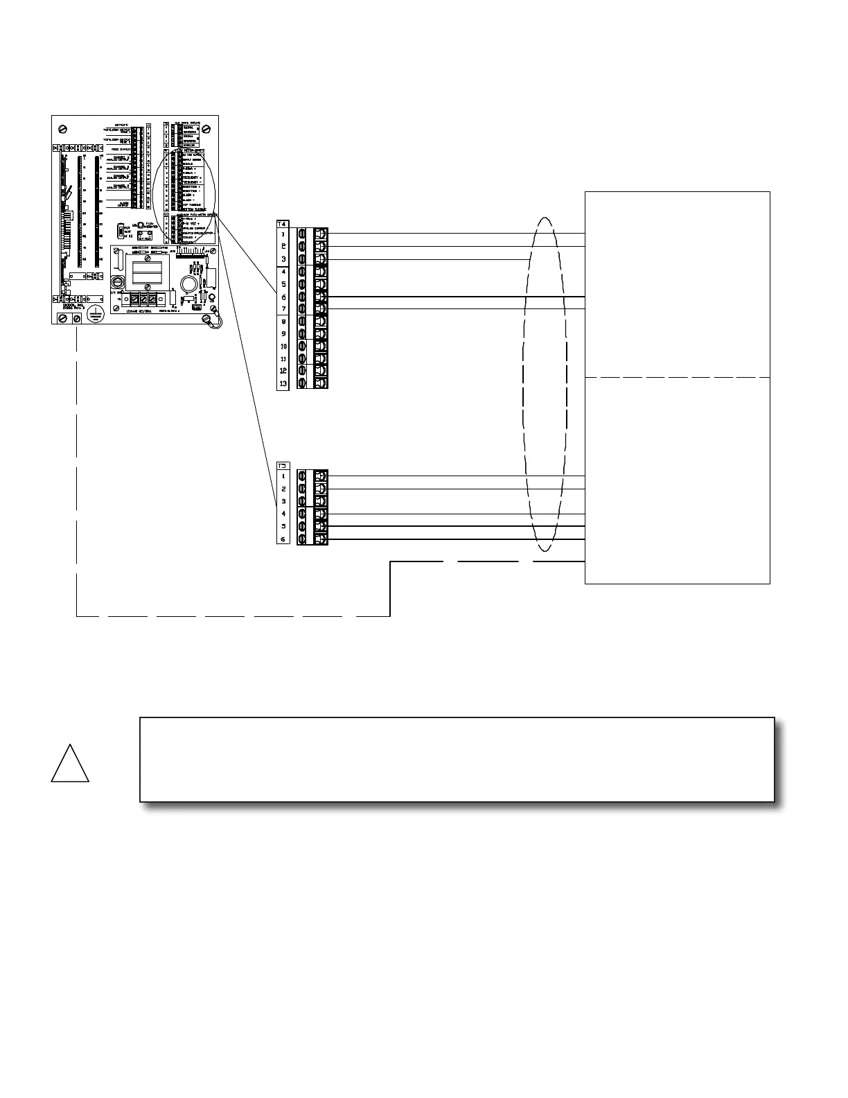
Connections shown for T5-1 and T5-2
are for the same analog output from the
F-3500. This output can be configured in
the flow meter as a 4-20mA or 0 -10
VDC.
0-10 VDC + (Blue)
* Frequency - . (Yellow)
* 24VDC Supply + (Red)
* Supply Common - (Black)
* Frequency + . (Green)
F-3500 Flow Meter Connections
Connections shown with * are
required for all models.
Connections shown with (A)
are required for all
bi-directional models.
Connections shown with (B)
are required for all dual turbine models,
including bi-directional.
4-20mA + (Blue)
Scaled + (Gray)
Scaled - (Violet)
Flow Meter Inputs
* Shield
Auxiliary Flow Meter Signals
Connections shown are for flow meter
output signals not used by the display.
Both incoming and outgoing connections
are made to the same terminal.
Isolated Analog Common - (Brown)
*Earth (Green/Yellow)
CAUTION
Shield and earth connections are required for proper operation. Failure to use shielded cable
or to connect earth to both the ow meter and D-100 may result in erratic operation. Shields
should be terminated at the D-100 shield terminals and left unterminated at the ow meter.
ONICON F-3500
Factory Installed Cable
3.3.1.2 ONICON F-3500 Flow Meters