1500 North Belcher Road, Clearwater, FL 33765 • Tel (727) 447-6140 • Fax (727) 442-5699 • sales@onicon.com
D-100 Flow Display Manual 08/12 - 0634-7 Page 18
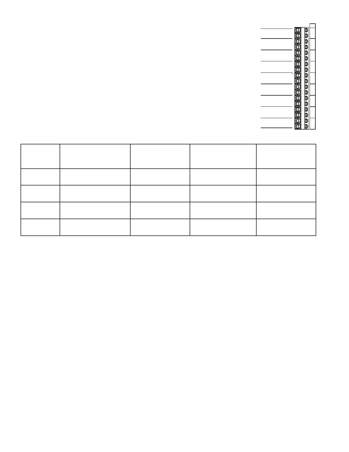
3.3.7 Totalizer Outputs and Mode Status
For unidirectional ow applications, the output relay for ow
total is located on the mother board at T1, terminals 1 and 2
(mode 1). The value of each “closure” is listed on the conguration
data sheet and is the same as the ow total multiplier displayed
on the LCD (example: each closure = 100 Gallons). This
information is also included on a label inside the D-100. For
bi-directional ow applications, connections for the mode 1 ow
total output relay are at T1 terminals 1 and 2. The mode 2 ow
total output relay connections are at T1 terminals 3 and 4. Flow
direction is indicated by the mode status output (T1 pins 5 and 6).
The table below describes the relationship between mode 1 and
mode 2 totals and forward and reverse ow for ONICON
insertion turbine and inline electromagnetic ow meters. Do not
exceed 4.5 in-lb (0.5 Nm) of torque, when tightening the terminals.
Flow Meter
Model
Flow Direction
Relative to Direction
Arrow on Meter
Flow Meter
Output Condition
D-100 Mode
Status Indicator
(T1 - Pins 5 & 6)
D-100 Register
Accumulating
Totals
FB-1200
Series
Flow in the direction
of arrow
Closed contact Open contact Mode 1
FB-1200
Series
Flow reverse from
direction arrow
Open contact Closed contact Mode 2
F-3000
Series
Flow toward (+) sign
Not energized
(open)
Closed contact Mode 2
F-3000
Series
Flow toward (-) sign
Energized
(closed)
Open contact Mode 1
3.3.8 Isolated Analog Outputs
The D-100 can be congured to provide up to four isolated analog outputs. These
outputs can be used to replicate the incoming analog signals. The output signal type
canbe4-20mA,0-10VDCor0-5VDCandiseldcongurable.ContactONICONfor
assistance in reconguring or reprogramming the analog inputs. See the conguration
data sheet provided or the label located inside the D-100 for output specic conguration
information. Analog output signal connections are made at T1 terminals 7 through 14.
Do not exceed 4.5 in-lb (0.5 Nm) of torque, when tightening the terminals.
OUTPUTS
TOTALIZER OUTPUT
MODE 1
TOTALIZER OUTPUT
MODE 2
MODE STATUS
CHANNEL A
ANALOG OUTPUT
CHANNEL B
ANALOG OUTPUT
CHANNEL C
ANALOG OUTPUT
CHANNEL D
ANALOG OUTPUT
ALARM
OUTPUT
+
_
+
_
+
_
+
_
T1
1
2
3
4
5
6
7
8
9
10
11
12
13
14
15
16
17
18