1500 North Belcher Road, Clearwater, FL 33765 • Tel (727) 447-6140 • Fax (727) 442-5699 • sales@onicon.com
D-100 Flow Display Manual 08-12 - 0634-7 Page 11
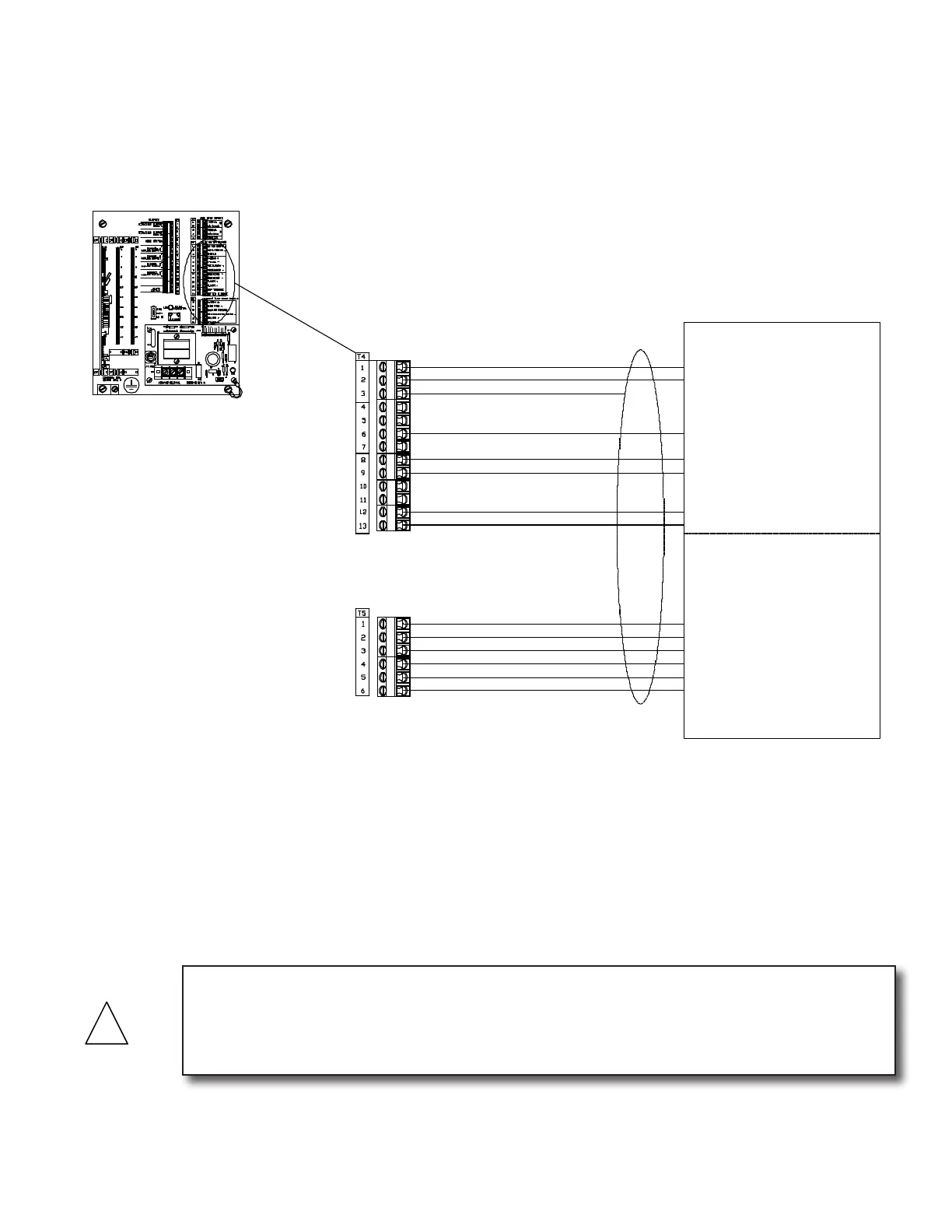
ONICON Turbine Flow Meter
Factory Installed Cable
ONICON turbine flow meters are provided with a variety of output signals. Only the red,
green and black wires are required to power the flow meter and operate the display. For
bi-directional applications, the gray and violet wires are also required to indicate flow
direction.
* 24VDC Supply + (Red)
* Supply Common - (Black)
* Frequency + . (Green)
(A) Direction + (Grey)
(A) Direction - (Violet)
(B) Top Turbine (White)
(B) Bottom Turbine (Orange)
F-1100, F-1200 & F-1300 Series
Flow Meter Connections
Connections shown with * are
required for all models.
Connections shown with (A)
are required for all
bi-directional models.
Connections shown with (B)
are required for all dual turbine models,
including bi-directional.
(C or D) 4-20mA + (Blue)
(C or D) 0-10 VDC + (Brown)
(E) Scaled + (Blue)
(E) Scaled - (Brown)
For F-1x10, F-1x11 & F-1x30
Flow Meter Inputs
(C) Analog Common - (Black)
* Shield
Auxiliary Flow Meter Signals
Connections shown are for flow meter
output signals not used by the Btu meter.
Both incoming and outgoing connections
are made to the same terminal.
(D) Isolated Analog Common - (Yellow)
Connections shown with (C)
are used with F-1x10 models, including
bi-directional.
Connections shown with (D)
are used with F-1x11 models, including
bi-directional.
Connections shown with (E)
are used with F-1x30 models, including
bi-directional.
CAUTION
Shield connections are required for proper operation. Failure to use shielded cable or to properly
terminate shield connections may result in erratic operation. Shields should be terminated in
the D-100 at the terminals provided. The shield connection at the ow meter should be left
unterminated.
3.3.1.1 ONICON Turbine Flow Meters
ONICON turbine ow meters are provided with a number of different output
congurations. These affect the number of wires contained in the cable attached
to the ow meter. Refer to the diagram below and the laminated tag attached to
the ow meter for specic details.
• TopandbottomturbinesignalsareonlyusedwiththeF-1200andFB-1200
ow meters.
• DirectionalcontactsareonlyusedbyFB-1200owmeters.
• Terminalblockpositionsareprovidedforadditionalowmetersignalsthat
may be available, but they are not used by the D-100.