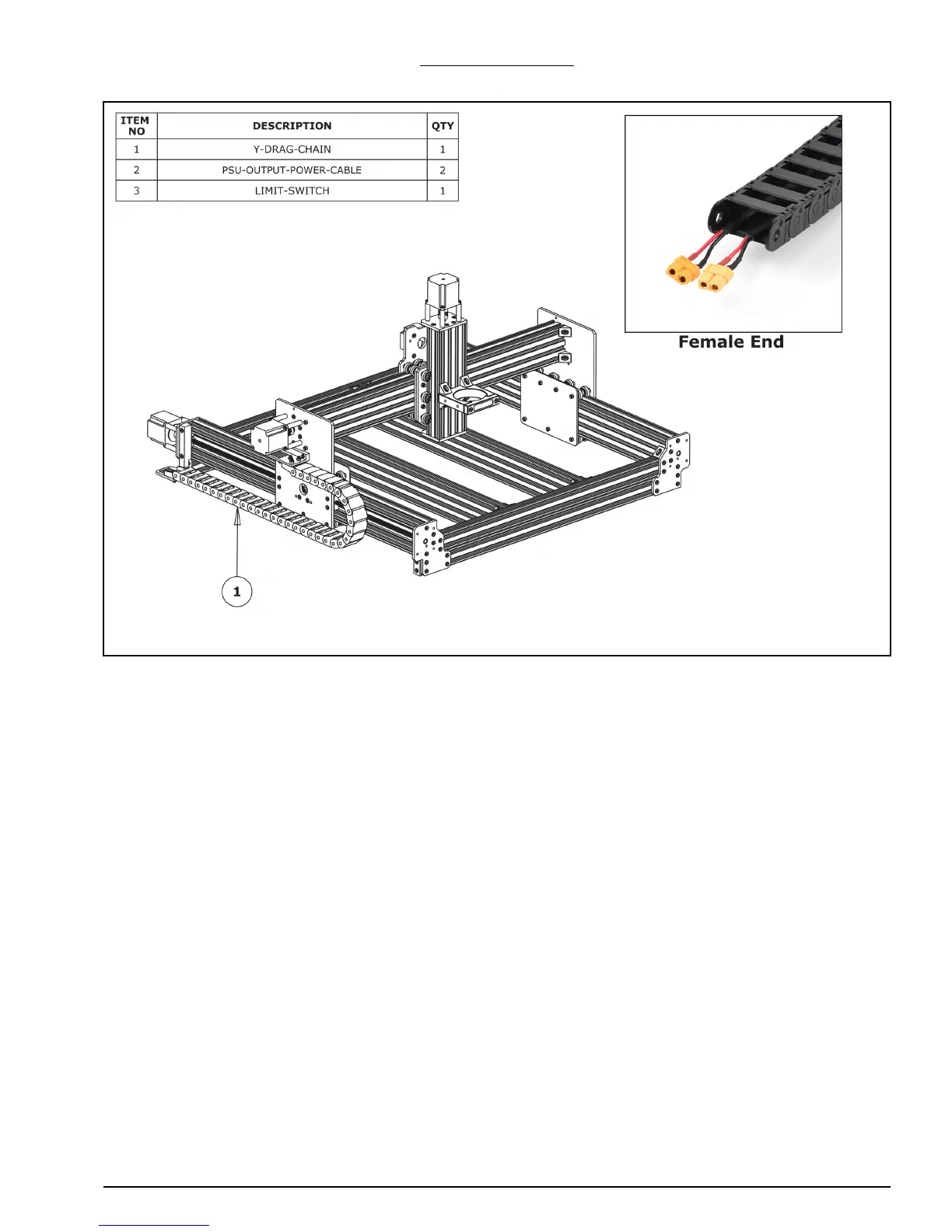
WorkBee CNC Drag Chains Assembly 11
2.1.5 Y-Drag-Chain
A. Lay the Y-Drag-Chain flat on a table. Feed one of the PSU-Output-Power-Cables
through the whole length of the Y-Drag-Chain. Ensure that the end with the XT60-
Connector, is located at the female end of the Y-Drag-Chain (as shown above in the
‘Female End’ image). Repeat for a second PSU-Output-Cable. If the PSU-Output-
Power-Cable gets snagged inside the Y-Drag-Chain, the tabs on the Y-Drag-Chain flip
open for access.
B. If you have a screw driven WorkBee only feed two stepper motor wires through the Y-
Drag-Chain. The end of the stepper motor wires with the black connector should be at
the female end of the Y-Drain-Chain - same as Step A. Further to this, one of the step-
per motor cables will be considerably longer than the other three - this cable should
be one of the two which go inside the Y-Drag-Chain.
C. For all WorkBee Variants, feed the wires on a Limit-Switch, through the Y-Drag-Chain.
The switch portion of the Limit-Switch should be at the female end of the Y-Drag-
Chain.
D. Lay the Y-Drag-Chain flat along the left side of the WorkBee. The female end of the Y-
Drag-Chain should be at the back of the machine, and the male end at the front.
E. Attach the female end of the Y-Drag-Chain to the Drag-Chain-Fixed-End on the Y-Axis-
Fixed-End-Assembly. It will take some force to click it into the Drag-Chain-Fixed-End.
F. Bring the male end of the Y-Drag-Chain to the Y-Axis-Moving-End-Assembly and
attach it to the Drag-Chain-Moving-End. It will take some force to click it into the
Drag-Chain-Moving-End.
 Loading...