WorkBee CNC Power Supply Assembly 17
3.1 Output
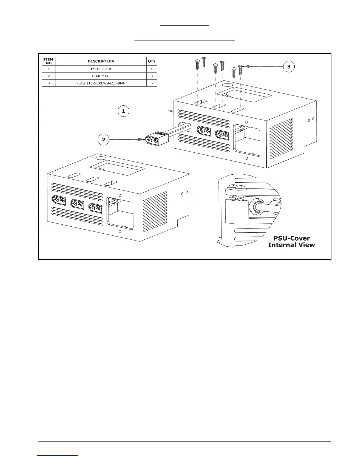
3.1.1 Securing XT60-Male Outputs
A. Insert the XT60-Male connectors into the provided insets on the PSU-Cover. They
should sit flush with the front of the PSU-Cover. Completion of this kit only requires 2
x XT60-Male connectors. The left-most XT60-Male connector is not needed for the
operation of this machine, but is included so you have the option to add additional
accessories. For safety reasons, if you do not intend to use it, do not attach it to the
PSU-Cover, and leave that inset empty.
B. Secure each XT-Male connector using 2 x Plastite-Screw-M2.5-8mm through the holes
provided on the securing tab as seen on the internal view. When initially placing the
screw, it is helpful to hold each screw in place using tweezers or long nose pliers.
 Loading...