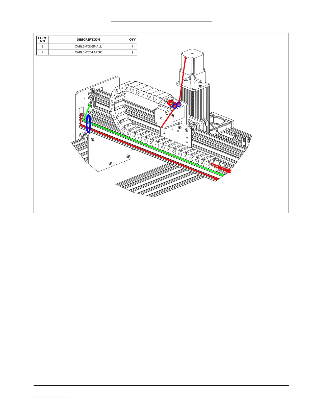
WorkBee CNC Limit Switches & Wire Routing 31
4.2.3 Belt Driven - Gantry Wire Routing
A. For one of the stepper motor wires that is inside the X-Drag-Chain, connect it to the
pigtail on Z-Axis stepper motor. Making sure there is enough slack for the full travel of
the Z-Axis, secure the wire to the X-Drag-Moving-End-Mount using a Cable-Tie-Small,
shown by the small blue circle above.
B. For the second stepper motor wire connect it to the pigtail on the X-Axis stepper
motor wire. Secure it to the X-Drag-Moving-End-Mount in a similar fashion as in Step
A
C. Connect a stepper motor wire to the pigtail on the right hand Y-Axis stepper motor (as
if looking from the front). Feed it through the square hole on the Y-Plate. The lead on
the X-Axis limit switch and stepper motor wire should be secured to the V-Slot-2040-
750mm using a Cable-Tie-Large at the position shown by the blue oval above. Then
run the wires along to the other end of V-Slot-2040-750mm - they can be tucked into
the slots.
 Loading...