WorkBee CNC Wiring & Commissioning 46
6.3 Testing
A. Next to each driver on the CNC-xPro, there is a current control pot, and these can be
adjusted using the Ceramic-Screwdriver. Rotate clockwise to increase the current, and
anti-clockwise to decrease. Turn each one clockwise until it stops, and then back 1/8th
of a full turn. This is the ideal setting for the drivers.
B. Switch on the 24V-360W-Power-Supply, and the 2 x 30mm-24V-DC-Fan’s should acti-
vate. If they do not activate, check the wiring in Step 5.0.4. If the machine is in an
alarm state press the $X button.
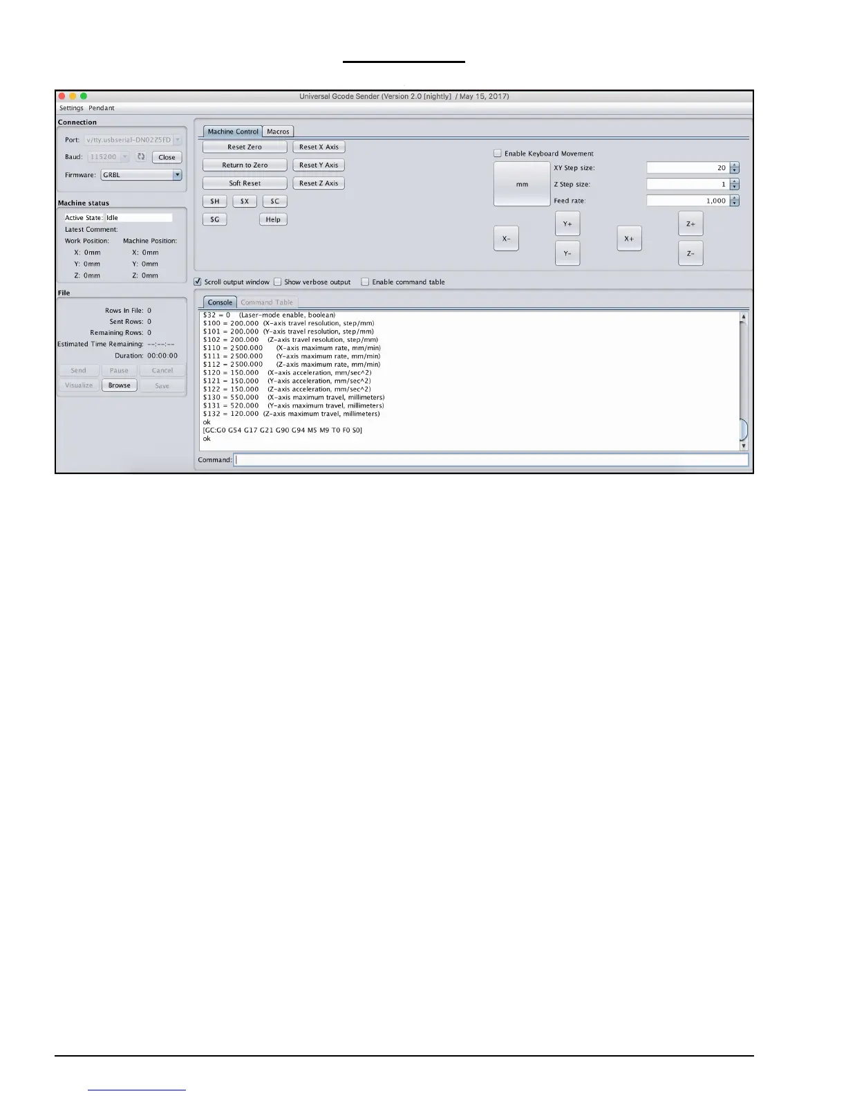
C. Looking from the front of the machine, the correct axes machine motion is: X-Axis
positive to the right, Y-Axis positive going away, Z-Axis positive going up. To test this
in UGS, click on the ‘Machine Control’ tab on the top bar. On the right hand side there
are jog controls. Set the ‘XY Step size’ to 20, ‘Z Step size’ to 1, ‘Feed Rate’ to 1000
and select ‘millimeters’. Press the ‘X+’ button to jog the machine in the positive X
direction, and the carriage should move to the right. Press ‘Y+’ and the gantry should
move away. Press ‘Z+’ the Z-Axis should go up.
D. If in Step C any of the axes have moved in the opposite directions than should be
expected, then the appropriate driver direction needs inverting. The $3 Direction Port
Invert setting can be used to correct this issue, this is set by using the table in Appen-
dix B section 2. For instance for a screw drive machine $3 currently is set at 2, setting
$3 = 3, would invert the X Axis direction, but leave all the others as they are. Change
$3 to the appropriate setting to get all the axes moving in the correct direction.
E. Next the homing cycle needs to be checked. Press the button labeled ‘$H’, this is the
Home button. The machine should first move positive upwards, and seek the Z limit
switch. Once it has located the Z limit switch, the X-Axis should begin homing to the
right, and the Y-Axis should begin homing to the back. Once the machine has located
all 3 limit switches, it should pull off them by 3mm. If the machine homes in the incor-
rect direction on any of the axes, change setting $23 using Appendix B section 2 in the
same fashion as Step D. If the machine fails to stop at any of the limit switches check
that they are wired correctly according to Section 6.1
 Loading...