WorkBee CNC Limit Switches & Wire Routing 33
4.2.5 Screw Driven - Y-Axis Wire Routing - Part 2
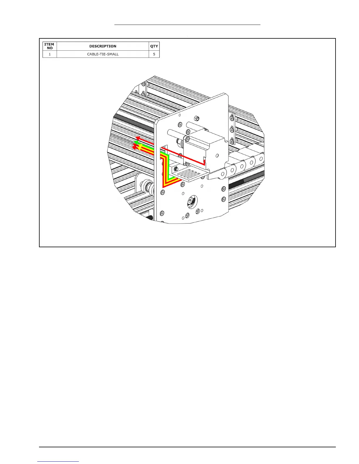
A. Connect a stepper motor wire to the pigtail on the X-Axis stepper motor and feed it
through the square hole on the Y-Plate
B. Inside the Y-Drag-Chain there should be two stepper motor wires (red above), two
power supply wires (yellow above), and a limit switch wire (green above). Feed all of
these through the square hole on the Y-Plate. Remove any slack inside the Y-Drag-
Chain, and then secure these 5 wires to the Y-Drag-Chain-Moving-End-Mount using
Cable-Tie-Smalls.
 Loading...