WorkBee CNC CNC xPro Assembly 39
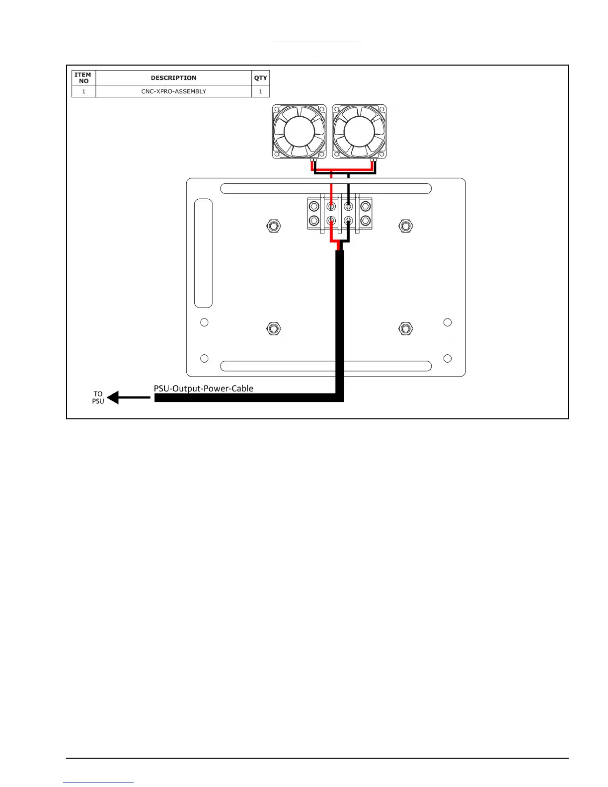
5.0.4 Fans Wiring
A. Locate both red wires coming from the two 30mm-24V-DC-30mm-Fans, and strip
approximately 20mm of sheaving. Twist the two exposed copper cores together to
form one.
B. Connect the red wires from the 30mm-24V-DC-30mm-Fans to the Terminal-Block, as
shown above. To connect a wire, unscrew the respective screw from the Terminal-
Block. Bend the exposed copper core of the wire around the screw. Screw the screw
back into the Terminal-Block.
C. Repeat Step A & B for the two black wires of the 30mm-24V-DC-30mm-Fans.
D. With one of the PSU-Output-Power-Cables already positioned on the machine, strip
back approximately 50mm of the black sheaving from the bare end to expose the red
and black wires underneath. Strip back approximately 20mm of the sheaving from the
red and black wires to expose the conductive core underneath. Connect these wires to
the Terminal-Block as in Step B.
 Loading...