WorkBee CNC Power Supply Assembly 24
3.3.3 Testing
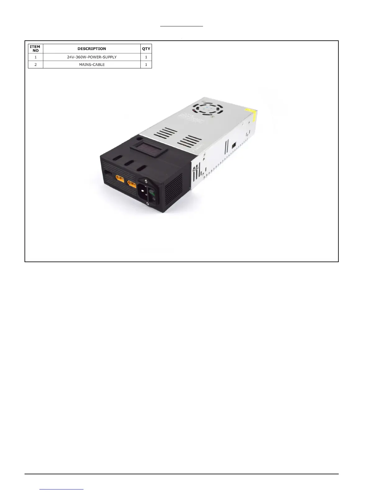
A. Insert the end of the Mains-Cable into the IEC-Inlet on the 24V-360W-Power-Supply.
B. Plug the Mains-Cable into a wall socket and switch it on. If the LED-Volt-Meter comes
on, this indicates the 24V-360W-Power-Supply has power. If it doesn’t come on, this is
most likely because the switch on the IEC-Inlet is turned off; turn this on.
C. Once switched on, the LED-Volt-Meter should read 24.0. If it does not read 24.0, the
screw through the hole towards the top left of the LCD can be used to adjust the volt-
age. Use a screwdriver to adjust the voltage to 24.0, and take caution to not touch
any metal parts with the screwdriver.
D. The Power Supply assembly is now complete and can be turned off and placed
towards the back left of the machine near, the Y-Axis-Fixed-End-Assembly.
 Loading...