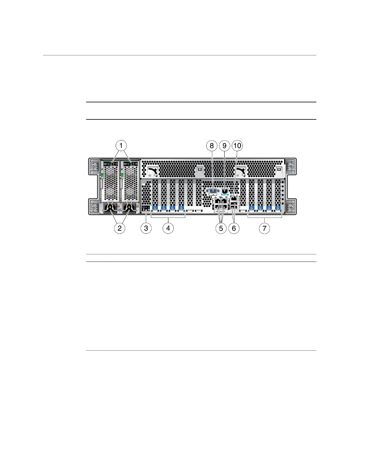
Rear Panel Components (Installation)
Rear Panel Components (Installation)
Note - You must follow the proper sequence when connecting cables to the server. Do not
connect the power cords until all data cables have been connected.
No. Description No. Description
1 Power supply unit 0 and 1 (from left to right) status
indicator LEDs:
■ Service Required (amber)
■ AC OK (green or amber)
6 USB 3.0 connectors (2)
2 Power supply unit 0 and 1 (from left to right) AC inlet 7 PCIe slots 5–8
3 System status LEDs:
■ Locate LED/Locate button (white)
■ Attention (amber)
■ Power/OK (green)
8 HD-15 video connector
4 PCIe slots 1–4 9 SP SER MGT RJ-45 serial port
5 Network 100/1000/10000 ports: NET0–NET3 10 SP NET MGT RJ-45 network port
Related Information
■
“Front Panel Components (Installation)” on page 12
■
“Cabling Requirements” on page 41
■
“Install the CMA” on page 35
■
“Secure Cables to the CMA” on page 52
Understanding the Server 13

 Loading...