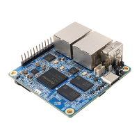
3) The function description of the 13 pin adapter board interface pins of the Orange Pi
Zero 2 development board is as follows
a. When the 13pin is connected to the adapter board, it can be additionally
provided
a) 2 USB2.0 Host
b) Headphone left and right channel audio output
c) TV-OUT video output
d) IR receiving function
e) After connecting the adapter board, pins 10, 11 and 12 of the 13pin
interface cannot be used
f) Also, note that the MIC on the 13pin adapter board cannot be used
on Orange Pi Zero2
b. When the 13pin is not connected to the adapter board, the 10, 11, and 12 pins
can be used as ordinary GPIO ports
3.18. Audio test
3.18.1. Headphone jack play audio test
1) First, you need to insert the 13pin adapter board into the 13pin interface of the
Orange Pi development board, and then insert the headset into the audio interface