3.23.4. SPI test
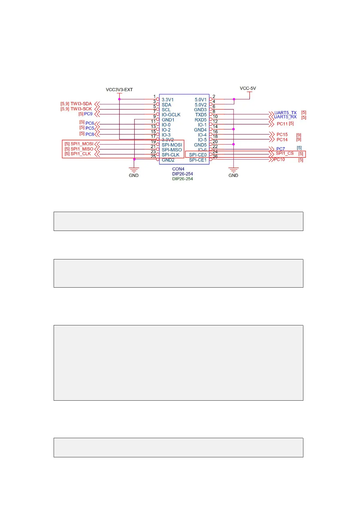
1) According to the schematic diagram of the 26pins connector, the available SPI for
Orange Pi Zero2 is SPI1
2) First check whether there is a spidev1.1 device node in the Linux OS. If it exists, it
means that SPI1 has been set up and can be used directly
root@orangepi:~/wiringOP/examples# ls /dev/spidev1*
/dev/spidev1.1
3) Compile the spidev_test test program in the examples of wiringOP
root@orangepi:~/wiringOP/examples# make spidev_test
[CC] spidev_test.c
[link]
4)Do not short-circuit the mosi and miso pins of SPI1 first, and the output result of
running spidev_test is as follows, you can see that the data of TX and RX are
inconsistent
root@orangepi:~/wiringOP/examples# ./spidev_test -v -D /dev/spidev1.1
spi mode: 0x0
bits per word: 8
max speed: 500000 Hz (500 KHz)
TX | FF FF FF FF FF FF 40 00 00 00 00 95 FF FF FF FF FF FF FF FF FF FF FF FF
FF FF FF FF FF FF F0 0D | ......@....▒..................▒.
RX | FF FF FF FF FF FF FF FF FF FF FF FF FF FF FF FF FF FF FF FF FF FF FF
FF FF FF FF FF FF FF FF FF | ................................
5) Then short-circuit the two pins of SPI1's mosi (the 19th pin in 26pins) and miso
(the 21st pin in 26pins) and run the output of spidev_test as follows, you can see that
the sent and received data are the same
root@orangepi:~/wiringOP/examples# ./spidev_test -v -D /dev/spidev1.1
spi mode: 0x0