Oscillator Phase Drift
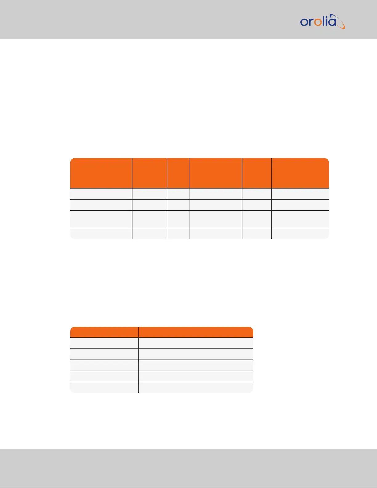
The chart below provides typical stability performance for the oscillator types that can be
found in VersaSync units. These numbers are based on the oscillator being locked to a ref-
erence for two weeks, but then loses GPS reception for an extended period of time, while
the ambient temperature remains stable.
This data can help you determine how long of a Holdover period can be tolerated, based on
how much time drift may occur after GPS input is lost. The larger the time error that can be
tolerated by VersaSync clients, based on the oscillator installed, the larger the Holdover
timeout period can be set to.
Table 3-3:
Estimated Phase Drifts
1PPS Phase Drift in
Holdover
(no reference avail-
able)
TCXO OCXO
Low Phase Noise
OCXO
Rubidium
Low Phase Noise
Rubidium
After 4 hours 12 µs 1µs 0.5 µs 0.2 µs 0.2 µs
After 24 hours 450 µs 25 µs 10 µs 1µs 1µs
After 7 days 3150 µs (3.1
ms)
175 µs 70 µs 7 µs 7 µs
After 30 days 13950 µs 775 µs 310 µs 31 µs 31 µs
To find out which type of oscillator is installed in your VersaSync, navigate to
MANAGEMENT > OTHER: Disciplining, and look for the line item Oscillator Type in the
Status panel.
Typical Holdover lengths
The length of the allowed Holdover Timeout period is displayed and configured in seconds.
The table below provides example conversions for typically desired Holdover periods.
Table 3-4:
Typical Holdover lengths in seconds
Desired Holdover Length Holdover Length (in seconds) to be entered
2 hours 7200 seconds (default value)
24 hours 86 400
7 days 604 800
30 days 2 419 200
1 year 29 030 400
196
CHAPTER 3 • VersaSync User Manual Rev. 7.0
3.3 Managing References