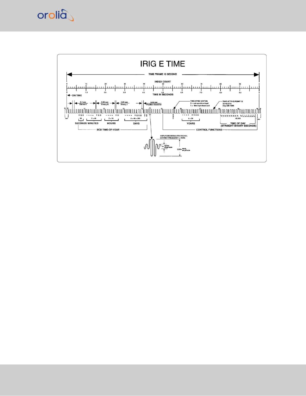
Figure 5-2: IRIG E time code description
Additional information
The beginning of each 10 second time frame is identified by two consecutive 80 ms ele-
ments (P
0
and P
R
). The leading edge of the second 80 ms element (P
R
) is the "on time"
reference point for the succeeding time code. 1PPS position identifiers P
0
, P
1
… P
9
(80ms
duration) occur 0.1s before 1PPS "on time" and refer to the leading edge of the suc-
ceeding element.
The time code word and the control functions presented during the time frame are pulse-
width coded. The binary "zero" and index markers have a duration of 20ms, and the binary
"one" has a duration of 50ms. The leading edge is the 10 pps "on time" reference point for
all elements.
The binary coded decimal (BCD) time-of-year code word consists of 26digits beginning at
index count 6. The binary coded subword elements occur between position identifiers P
0
and P
5
(3 for seconds; 7 for minutes; 6 for hours; 10 for days) until the code word is com-
plete. An index marker occurs between the decimal digits in each subword to provide sep-
aration for visual resolution. The least significant digit occurs first. The BCD code recycles
yearly.
Forty-five control functions occur between position identifiers P
5
and P
0
. Any control func-
tion element for combination of control function elements can be programmed to read a
VersaSync User Manual 339
APPENDIX