37
Reducing the required space
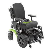
1) Set the battery packs back into the drive unit brack
et.
INFORMATION: Ensure that the red arrows on
the battery packs point forward.
2) Fold the lock lever up again to prevent the battery
packs from falling out (see fig.37).
3) If needed: Lay the control panel on top of the bat
tery packs (not illustrated) or insert it into the cor
responding holder.
INFORMATION: Ensure that the control panel is
not switched on and that cables are not
pinched.
→ Now the power wheelchair is ready to transport
and can be stowed in a vehicle.
38
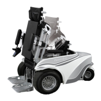
Disassembling the power wheelchair for transport
ation
The power wheelchair can also be fully disassembled
for transportation. This has the following advantages:
• It takes up very little transportation space.
• The power wheelchair disassembled into single
components is easier to handle.
• NOTICE: Secure the disassembled parts of the
power wheelchair properly so that they cannot
slide.
8.15.3 Preparing for transport
Transporting the power wheelchair as a whole
1) If needed: Turn the control unit off (see Page23).
2) If needed: Lock the brake (see Page30).
3) Use cargo straps to attach the power wheelchair to the transport vehicle.
8.15.4 Assembly
To reassemble the power wheelchair, the steps described above must be carried out in reverse order.
If the frame was separated from the drive unit bracket for transportation of the power wheelchair, correct locking of
the frame has to be ensured during assembly:
39
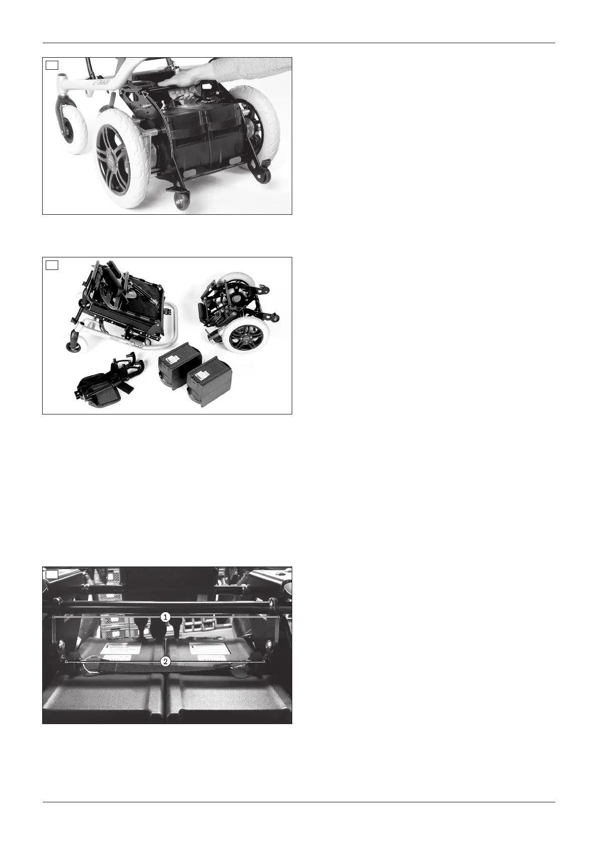
Connecting the frame to the drive unit bracket
1) Prepare the drive unit bracket and frame.
2) Pull the seat lock release strap and fold the locking
bar all the way down (see fig.34).
3) On the drive unit bracket, push down on the step
points (frame protection rollers) above the anti-tip
per rollers until these touch the ground (see fig.35,
left). The drive unit bracket is now at an angle.
4) Set the frame onto the drive unit bracket from above
(see fig.35, right).
45A200
Use