Installation
20
900-0209-01-00 Rev A
A
UX
terminals 5 and 6 are the A
UX
output – and + terminals. These terminals are colored gray (–) and
orange (+) for easy reference. The terminals can supply up to 250 mA at 12 Vdc (3 W). This circuit
contains electronic overcurrent protection, which resets after being overloaded. No additional fuses are
required for A
UX
terminals.
The A
UX
indicator illuminates when the output becomes active. (See page 30 for a description of the LED
indicators and their functions.)
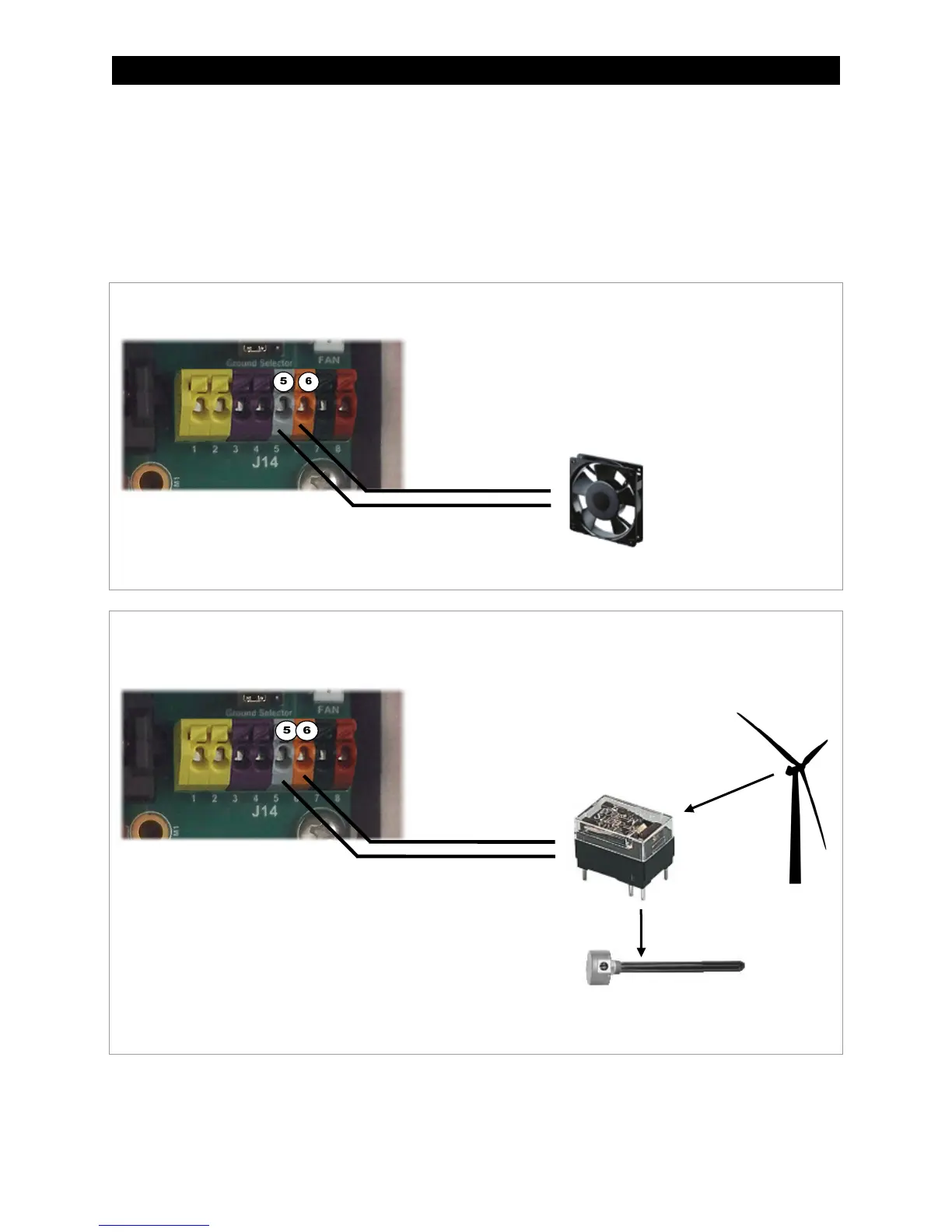
Examples of AUX wiring
Figure 11 AUX Vent Fan
Figure 12 AUX Diversion Control
In this example, the AUX output directly drives a 12-volt vent fan. The – and + wires on the fan are connected to AUX terminals
5 and 6, the A
UX– and AUX+ terminals.
In this example, the AUX drives a relay that diverts wind power. The relay’s coil is connected to AUX terminals 5 and 6, the
A
UX– and AUX+ terminals. When the AUX output closes the relay (based on battery voltage), the relay diverts excess power to
a water heating element.
Relay
Element
Turbine
NOTE: Relays and elements shown are examples only and
may vary depending on the installation.