Installation
22
900-0209-01-00 Rev A
Wiring Diagrams
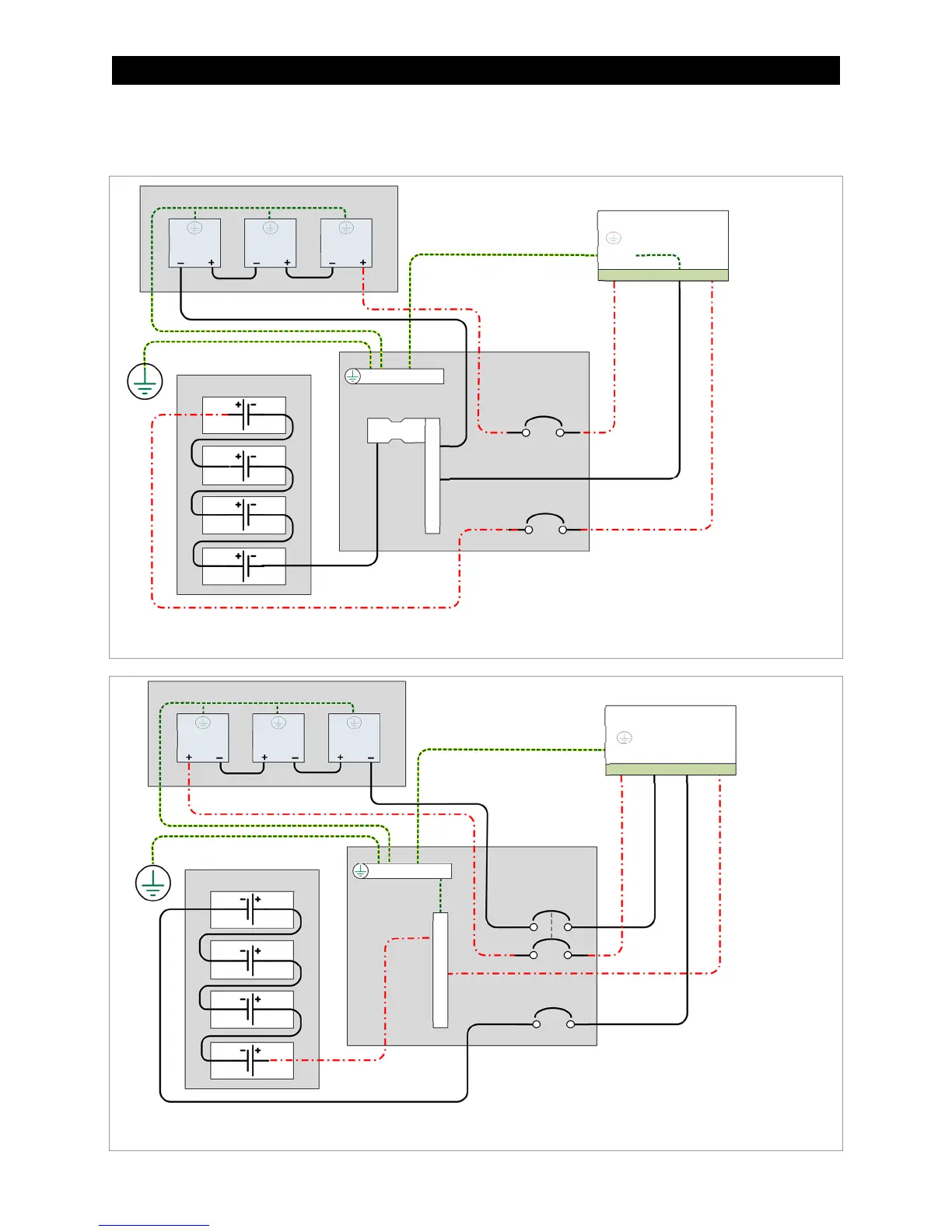
Figure 14 Wiring Diagram – Single Charge Controller with PV Array
Figure 15 Wiring Diagram – Single Charge Controller (Positive-Ground)
NOTES: System-specific wiring is not shown.
This image shows a single (common) negative conductor
instead of separate BAT– and PV– conductors.
Photovoltaic (PV)
Charge Controller
Battery Bank
PV
PV PV
Ground Bus Bar
Shunt
DC Negative Bus Bar
Ground
PV+ PV– BAT– BAT+
DC
Disconnect
Panel
NOTES: The PV circuit is shown protected with a dual-pole
circuit breaker. Positive-ground bond is shown external to the
controller. System-specific wiring and GFDI are not shown.
Photovoltaic (PV) Array
Charge Controller
Battery Bank
PV
PV PV
Ground Bus Bar
DC Positive Bus Bar
Ground
PV+ PV– BAT– BAT+
DC
Disconnect
Panel