Installation
900-0209-01-00 Rev A
25
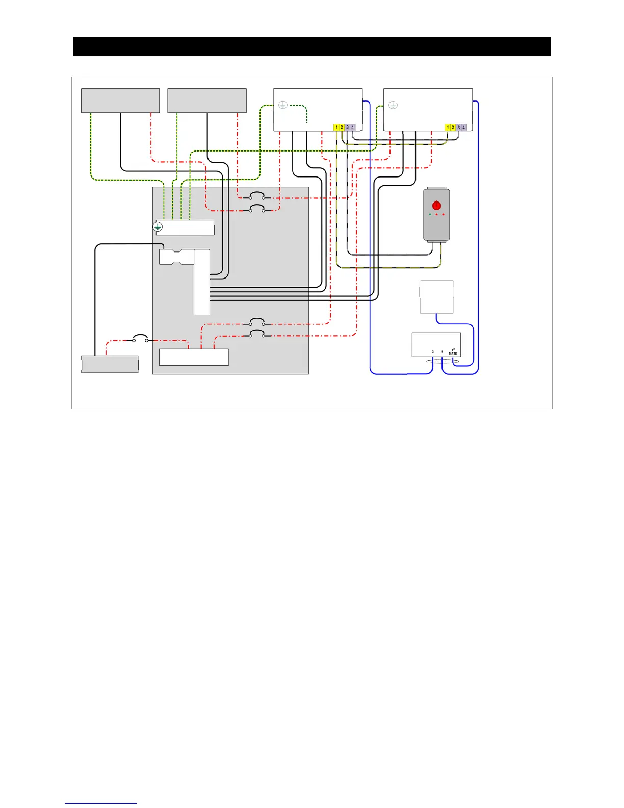
Figure 18 Two Charge Controllers with Rapid Shutdown
If multiple charge controllers are in use, they can be paralleled so that all controllers use a common
rapid-shutdown circuit. Terminals 2 and 4 are a parallel set of connections to terminals 1 and 3.
In Figure 18, Charge Controller A terminal
1
is wired to one of the RSI terminals. Terminal
3
is wired to the
other RSI terminal.
In Figure 18, Controller A also shows terminals
2
and
4
wired to Controller B terminals
1
and
3
.
~ This places the Rapid Shutdown circuits on both controllers in parallel. It allows Controller B to sense the
same conditions as Controller A so that it will react accordingly.
~ If a third controller is present, its terminals 1 and 3 should have wires connecting to terminals 2 and 4 on
Controller B, and so on.
~ Additional controllers can be added as needed.
The terminals detect electrical continuity, which is present while the RSI contacts remain closed. If a
rapid shutdown event occurs (the RSI switch is thrown and the PV is disconnected), these contacts will
open and the circuit will detect the loss of continuity. When the controller senses loss of PV input (less
than 20 Vdc), it will shut down. All LED indicators will flash twice and then turn off. (See pages 30 and
55.) If the system display is present, it will deliver a Fault Input Active error message. (See page 38.)
NOTE: To reset the controller after a rapid shutdown, simply reset the shutdown device.
NOTE: Bonding
umper is shown in
negative-ground
position in the first
controller only.
System-specific
wiring is not
shown.
PV Array A
HUB
Charge Controller A
DC
Disconnect
Panel
RSI
Battery Bank
CAT 5E
HUB
PV+ PV– BAT– BAT+
Ground Bus Bar
Shunt
Terminal Bus Bar
(Negative)
Terminal Bus Bar
(Positive)
MATE3s
Ground
Control Wiring
Terminal Block
PV Array B
Charge Controller B
HUB
PV+ PV– BAT– BAT+
Ground
Control Wiring
Terminal Block