30 900-0209-01-00 Rev A
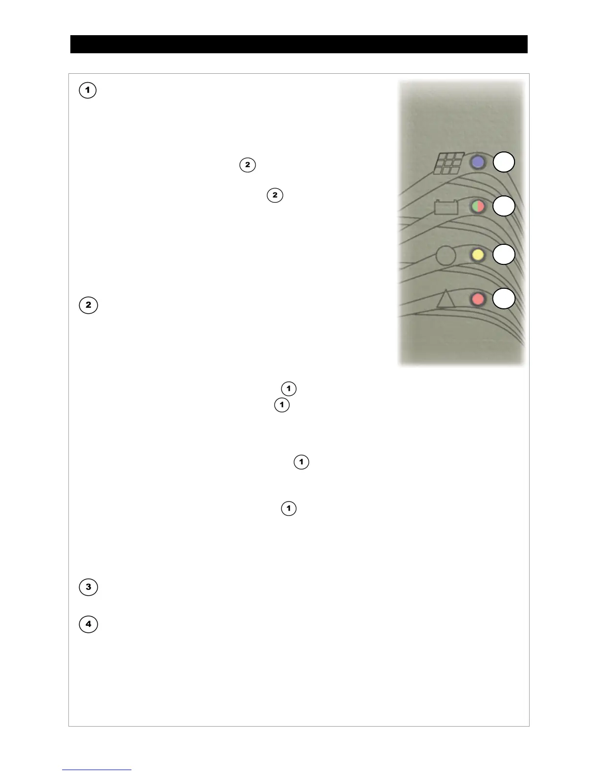
Figure 19 LED Indicators
CHARGE (Blue):
Illuminates when more than 10 watts of PV power is available. It is solid or
flashing depending on the charging stage. The system display represents
these stages as operating modes in the
STATUS menu. See page 36 for a
65 for a description of charging stages.
: Bulk or Equalization charging.
• Accompanied by
S
TATUS
indicator
. See below for colors.
: Absorption or Float charging.
•
Accompanied by amber
S
TATUS
indicator in Absorption stage.
•
Accompanied by green
S
TATUS
indicator in Float stage.
•
Will continue flashing in these modes even if less than 10 watts
is available.
•
The
STATUS
indicator flashes during power-up to indicate nominal
voltage. (See page 26.) It may briefly illuminate at other times when
not charging. (See Table 4 on page 34.)
: Less than 10 watts of PV power is available.
STATUS (Tri-color Red, Green, or Amber):
Indicate either battery voltage or charger status. See
Table 2 on page 29.
: Amber is a mixture of the red and green colors.
The battery voltage is equal or greater than 1.91 volts
• Usually indicates Bulk or Absorption stage.
•
Accompanied by solid blue
C
HARGE
indicator in Bulk stage.
•
Accompanied by flashing
C
HARGE
indicator in Absorption stage.
: The unit has entered Float stage.
• It will remain green regardless of the battery voltage until it falls below 2.08 Vpc. This will trigger a new
charge cycle.
•
Accompanied by flashing blue
C
HARGE
indicator .
: Indicates Grid-Tie mode. See page 44.
Amber/Green (alternating)
: Equalization mode.
•
Accompanied by solid blue
C
HARGE
indicator .
•
May also flash amber/red. (See pages 33 and 66.)
: The batteries are less than 1.91 Vpc. This indicates that the batteries are severely discharged.
: The batteries are less than 1.75 Vpc. This indicates that the batteries are critically discharged.
•
These states do not indicate the charging stage. It may still be shown by the blue
C
HARGE
indicator.
A
UX
(Yellow):
•
Solid
: The AUX output is active.
E
RROR
(Red):
•
Solid
: The GFDI circuit has shut down the charge controller. See page 15 for more information. If the
system display is present, it will deliver a
GFDI Fault
error message (see page 38). See Table 7
beginning on page 53 for information on resetting this error.
•
Flashing
: This indicator will flash twice to indicate a Rapid Shutdown. See page 19 and 24 for information.
All indicators will then go out until the Rapid Shutdown is reset. (See page 25.) If the system display is
present, it will deliver a
Fault Input Active
error message (see page 38).