B-149-4N-E
11
8. WIRING INSTRUCTIONS
8.1 Wiring Guidelines
(1) Cables for field wiring
The following cables should be used unless otherwise specied:
Use cables of conductor area 1.25mm
2
and nished O.D. 12mm, selecting from 2 to 4pcs. according to your
application. It is recommended that their shield be grounded at the receiving instrument.
CAUTION: In case of TIIS explosionproof type used under the ambient temperature of
50°C or higher, use a cable resistant to the temperature of 70°C or higher.
(2) Transmission length
The maximum transmission length is typically one kilometer.
NOTE: If it exceeds one kilometer, consult us.
(3) Inductive interference prevention
To minimize the possibility of stray current pickup, the eld wiring should be routed sufciently away from
existing power cables or power circuits.
(4) Considerations on connections
1) M3.5 terminal posts are used on the terminal block. Use crimp-style terminals that t the conductors at the
cable end.
2) Be sure to earth ground the preamplier's ground terminal.
3) Pitch down the cable from the cable entry so that rainwater will not have a chance to enter the equipment
through the cable.
4) In areas where lightning strokes are expected, provide a lightning arrestor for protection.
CAUTION: Make sure of the validity of meter (register) and receiving instrument
combination by referring to their model numbers, serial numbers, etc.
before you make electrical connections.
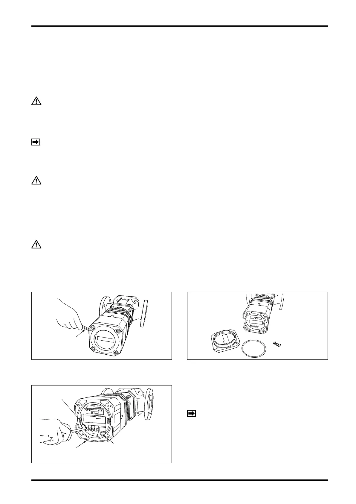
8.2 Terminal Connections
(1) Take off four hex socket head bolts (402) on the
front of register assembly and remove the cover
(401).
(2) Remove the cover to gain access to a 4-post
terminal block. Terminal identication is found on
the back of cover.
(3) Using crimped-lug terminals, ensure good
electrical connections.
COVER
HEX SOCKET
HEAD BOLTS
O-RING
REMOTE OUTPUT
TERMINALS
EXTERNAL GROUND
TERMINAL
INTERNAL GROUND
TERMINAL
NOTE:
1. Pressuretight packing is not furnished with non-
explosionproof models and non-output models
(see page 5).
2. Connect the external earth ground terminal to
instrumentation earth ground before use.
(Refer also to the wiring instructions of respective receiving instrument
instruction manual.)