B-149-4N-E
22
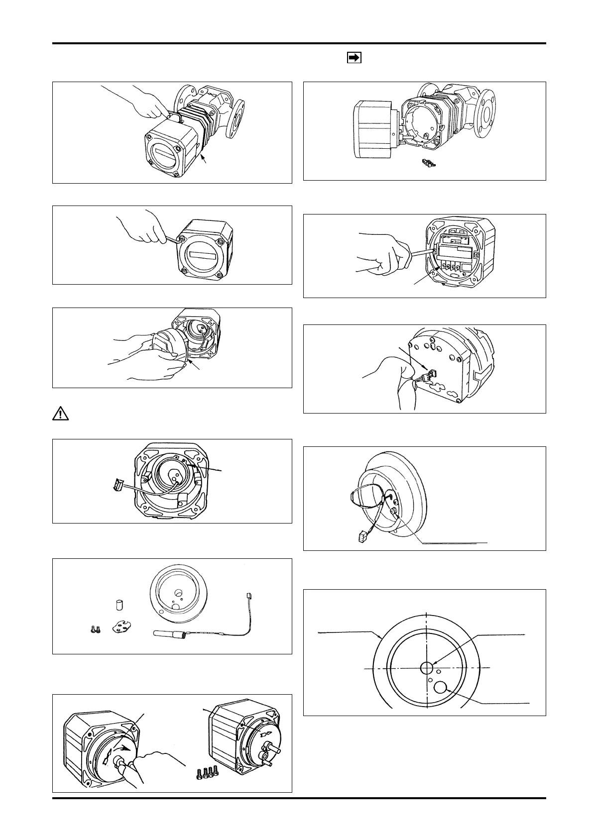
12. SENSOR REPLACEMENT PROCEDURE
NOTE: Size 55 meter body is shown here.
The same procedure applies to other size
models.
HEX SOCKET
HEAD BOLTS
REGISTER
ASSEMBLY
SENSOR RETAINER
FITTING SCREW
(1) Take off four hex socket head screws on the register.
(2) Carefully draw the register assembly out. Exercising care
not to bump the sensor against adjacent components,
draw it out in the horizontal direction.
(3) Take off four hex socket head bolts and separate the
cover.
(4) With screwdriver, take off two tting screws holding the
electronics unit
(5) Holding the electronics unit in both hands, carefully draw
it out.
CAUTION: Use extra care not to damage the leads
by forcibly pulling the sensor fitting disc.
(6) Uncouple the connector from the sensor unit at back of
the electronics unit.
(7) Using C-shaped stop ring pliers, remove the C-shaped
stop ring for the shaft. The sensor unit is now separable
from the register housing.
(8) Loosen the sensor retainer fitting screws (M4) with
screwdriver, remove the sensor retainer and draw out the
sensor unit.
(9) Install a new sensor unit through the opening through
which the old sensor unit was removed and assemble in
the reverse order of disassembly.
(10) At register installation in the meter body, match the ow
direction of the meter body with the arrow on the sensor
tting disc.
CONNECTOR
C-SHAPED
STOP RING
SENSOR
FITTING DISC
SENSOR UNIT
153
152158
LOCATION OF SENSOR INSTALLATION OPENING
SENSOR
FITTING DISC
SENSOR
OPENING
BLIND PLUG
(153)