B-149-4N-E
12
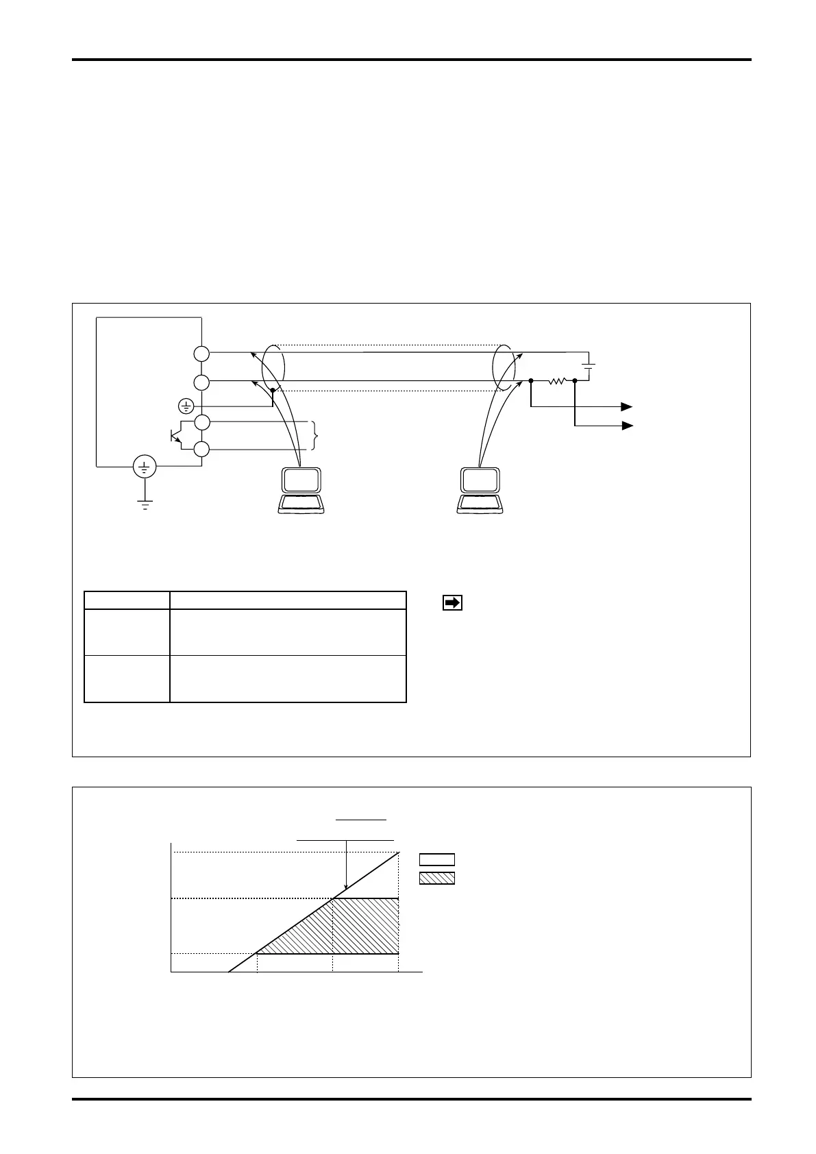
8.3 Preamplifier-to-Receiving Instrument Hookup
The 2-wire signal transmission system used in this owmeter furnishes DC power to the meter. It serves as the
power line and signal line as well with pulse or analog current output.
An OVAL receiving instrument can be coupled directly, but instruments in general which are designed to
accept a voltage signal input require a load resistor R
L
connected in series for voltage conversion. Since the
voltage signal level varies with the load resistance value, determine the load resistance value by referring to the
receiving instrument specications and the acceptable load resistance range shown below.
Communications with a PC (Smart Communication Unit) requires a 250 to 1000
Ω
load.
●
In case a voltage input is fed to the receiving instrument
Output Voltage Signal (V)
Pulse
Output
ON/OFF =
(20mA × R
L
) / (4mA × R
L
)
Analog
Output
(4mA × R
L
) − (20mA × R
L
)
at 0 ro FS
NOTE: With the relationship with supply
voltage E, select the load resistance
value R
L
such th a t th e cu r rent
flowing into the transistor is held
below 50mA.
Fig. 8.1
Supply Voltage (VDC)
Acceptable Load Resistance Range.
RL(Load Resist.)
0 12V
17.25V
45V
1000Ω
1571Ω
250Ω
33V
Area: Operating range
Area: Acceptable Communication range
R
=
L
E−12V
21mA
EXAMPLE:
If supply voltage is 24V DC with load
resistance 250Ω, then a 1 to 5V DC
output is obtained.
(
(
Fig. 8.2
L
PC POWER
R
+
−
VOLT. SIGNAL
TO RECEIVING
INSTRUMENT
+
−
OPEN COLLECTOR
OUTPUT
30V, 50mA max.
FLOWMETER
REGISTER
GND
+
−
2
1
4
3
+
−
(SMART COMMUNICATION UNIT)
(OR HHC:EK10)
PC
(SMART COMMUNICATION UNIT)
(OR HHC:EK10)
PC
R
L