B-149-4N-E
17
10.2 Size 50 Meter Body Assembly Procedure
CAUTION: PRECAUTIONS BEFORE ASSEMBLY
Oval rotors, inner walls of the rotor shafts, inner wall of the measuring chamber, inlet and outlet ports should be
thoroughly washed clean, completely removing dust, grime and other foreign matter.
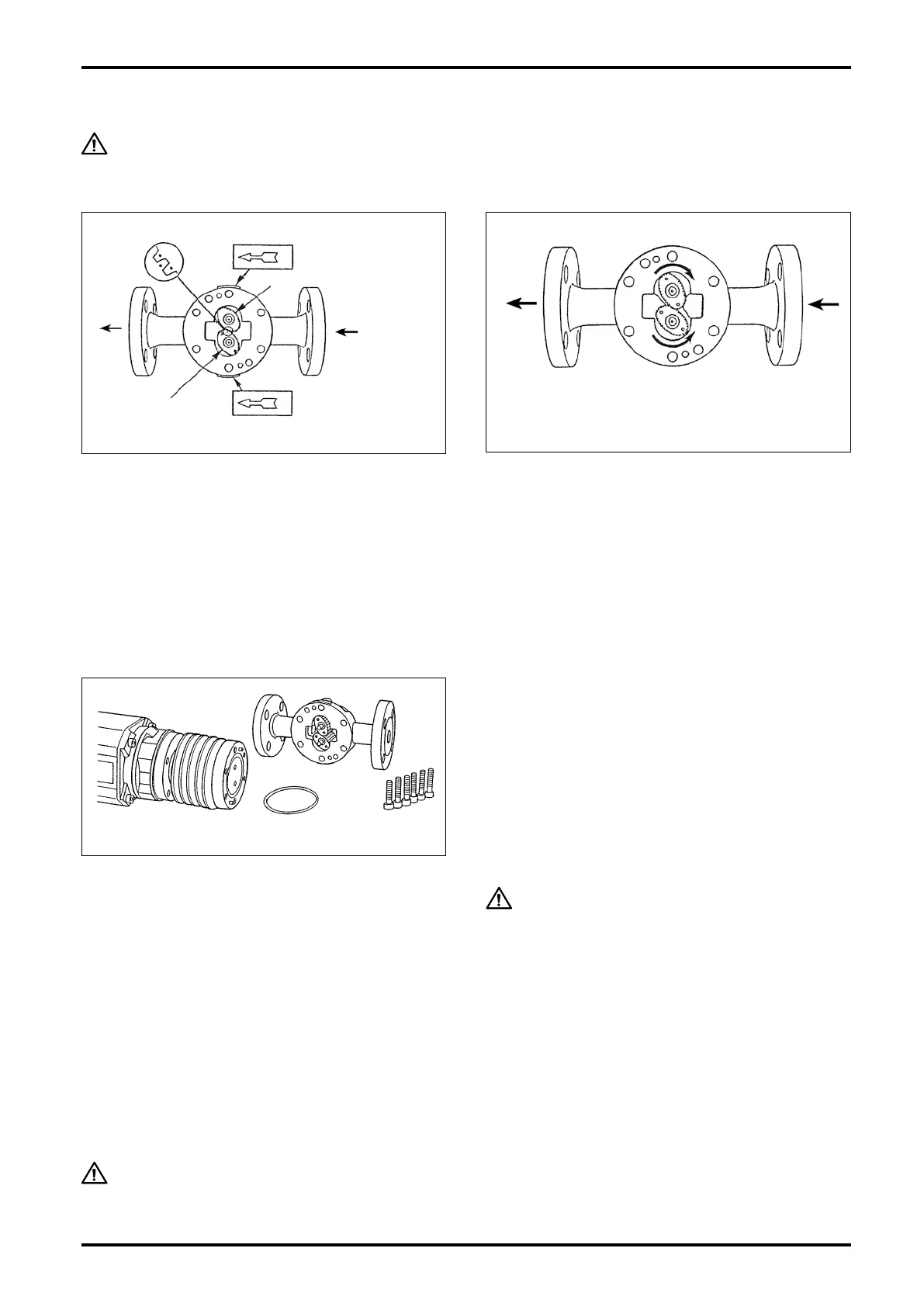
MATCH MARKS
1ST ROTOR SIG.
MAGNETS
IN
1
2
OUT
2ND ROTOR
FLOW DIR. ARROW AND
2ND ROTOR NO.
FLOW DIRECTION
FLOW DIR. ARROW AND
1ST ROTOR NO.
(1) Rotor Installation
Rotor installation is correct if the side where signal
generating magnets are embedded faces the register
(top in the measuring chamber) and the side with match
marks ( • ) ( • • ) faces the front cover.
Carefully install the rotors with the 1st rotor (match mark
" • ") on the shaft with "1" stamped on the outside of
measuring chamber and the 2nd rotor (match mark
" • • ") on the shaft with "2" stamped. Ensure that the
match marks are as shown in the inset.
Hot Water Jacketed Type, Horizontal Run
(2) Confirming the Rotor Gear Engagement
Hand rotate the rotors to make sure of correct gear
mask.
FRONT COVER
O-RING
HEX BOLTS
(REGISTER SIDE)
(3) Front Cover Installation
Firstly install O-ring (108) on the front cover. If the
O-ring is damaged or swollen with metered liquid, it
will not t in the groove. If such is the case, replace
with a new one.
Align the locating pin of front cover with its pin slot
in the meter body and, fitting the rotor shafts into
rotor shaft sockets in the front cover, force the meter
body until the locating pin ts rmly in the pin slot
in the meter body without slanting the front cover.
Install six front cover fitting bolts (M6) and tighten
them evenly until the front cover is closely in contact
with the meter body.
(4) Confirming Freely Rotation
With air or water, make sure to see that the rotors
move freely and that the register counts in response.
CAUTION
Rotation check should be performed at
low rotor r.p.m.
Violent rotor spinning may cause a
damage to the components, such as
bearing seizure.
CAUTION: Since the registers are not compatible each other, do not replace one
register with that of other meter.