B-149-4N-E
8
5.4 Total Counter Reset
Displayed total flow can be reset either by the display select switch SW1 (see Fig. 11.1 on page 20) or
through communications with the Smart Communication Unit. It your option is through communications, follow
the instructions outlined in the Smart Communication Unit EL2310 (or HHC: EK10) instruction manual.
NOTE: Show "Measure" window at "View" menu on the PC screen.
With the display select switch, then, you can reset the totalizer by holding the display select switch SW1
depressed for more than 3 seconds while the total ow is shown.
5.5 Considerations with Pulse Output Type
(1) If your model is of pulse output type, the pulse output and total counter remain inoperative for 15 seconds
approx. after power on and while communications with the Smart Communication Unit continue. For 15 seconds
approx. after termination of communications, the pulse output and total counter also remain inoperative.
(2) Requirements for validating communications
Communications are made valid only when the following requirements are met:
- Flowrate at zero (There is no pulse output.)
- Within 15 seconds after power turn-on
NOTE:
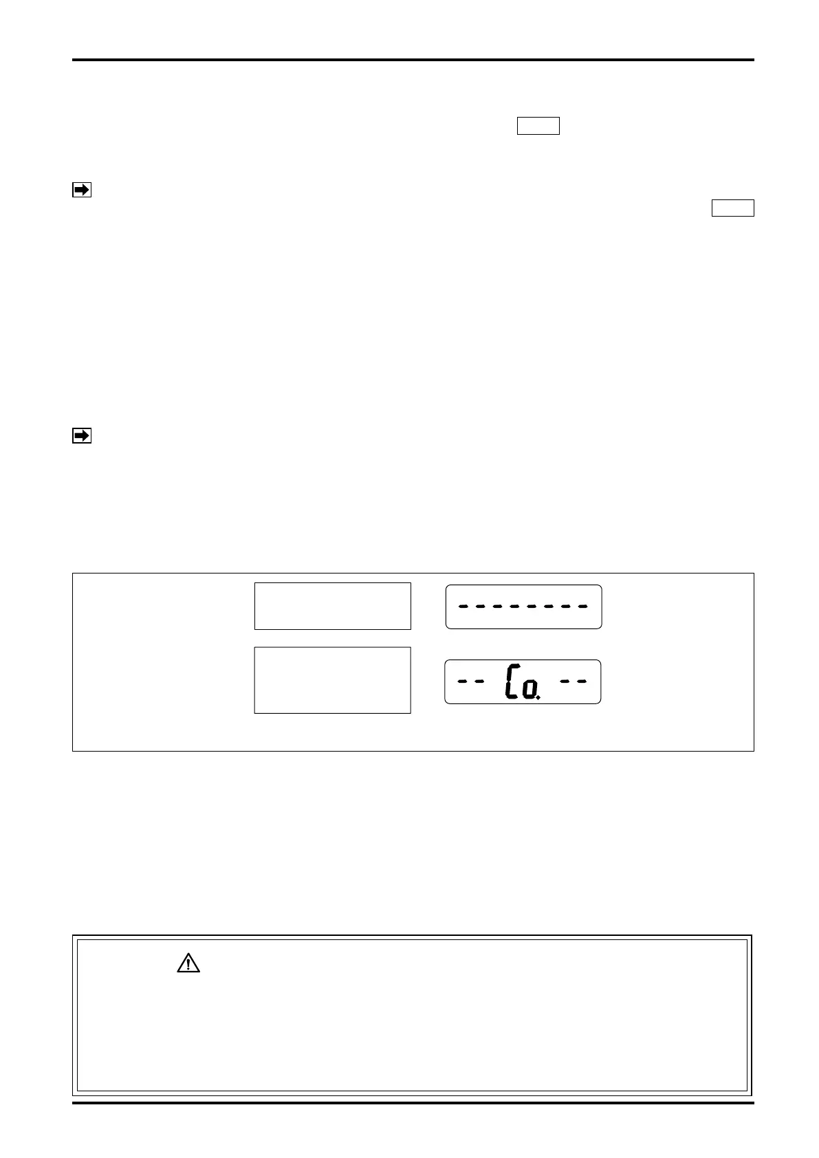
The period of 15 seconds immediately after power on is called "Communication standby mode." (The
built-in indicator, if so equipped, will display as shown in
①
in the gure below.)
If communications are started during this time period, a switchover to "Communication mode" takes
place, permitting you to communicate until power is turned off the next time. (The built-in indicator
will display as shown in
②
in the gure below.)
To start ow measurement routine, turn power on again. (After power cycling, the pulse output and
total counter will also remain inoperative for 15 seconds.)
(3) While communications continue, the receiving instrument (total counter, etc.) may overcount under certain
circumstances. To eliminate the possibility of such erratic extra counting, precautions should be taken by
either disconnecting the receiving instrument before starting communications, or recording the most recent
total reading and other important data on paper.
(4) Except for the purpose of communications, do not attempt to connect the probe of Smart Communication
Unit with the signal lines. If the probe remains connected, the influence of capacitive impedance the
interface has could go to the point of producing distorted signals in waveform and, as a result, the receiving
instrument would fail to receive pulse signals accurately.
CAUTION: PRECAUTIONS with ANALOG OUTPUT TYPE
The analog type permits communications with the Smart Communication Unit at any
time. However, if, in an attempt to alter current parameters, the meter is configured
by mistake such that the new parameters are incompatible with the specification,
resultant sharp changes in output may disturb the behavior of the receiving
instrument. It is good practice, therefore, to make parameter changes while the fluid
flow is at zero.
②
①
15 seconds after power on.
(Com Standby Mode)
Communication is started
within 15 seconds after
power on. (Com Mode)
Fig. 5.2 Display in Response to Power ON, Pulse Output Type