B-149-4N-E
21
11.2 Individual Test Pin Functions
NOTE: Connect the 0V end to the L.H. side fixed screw of the electronics unit.
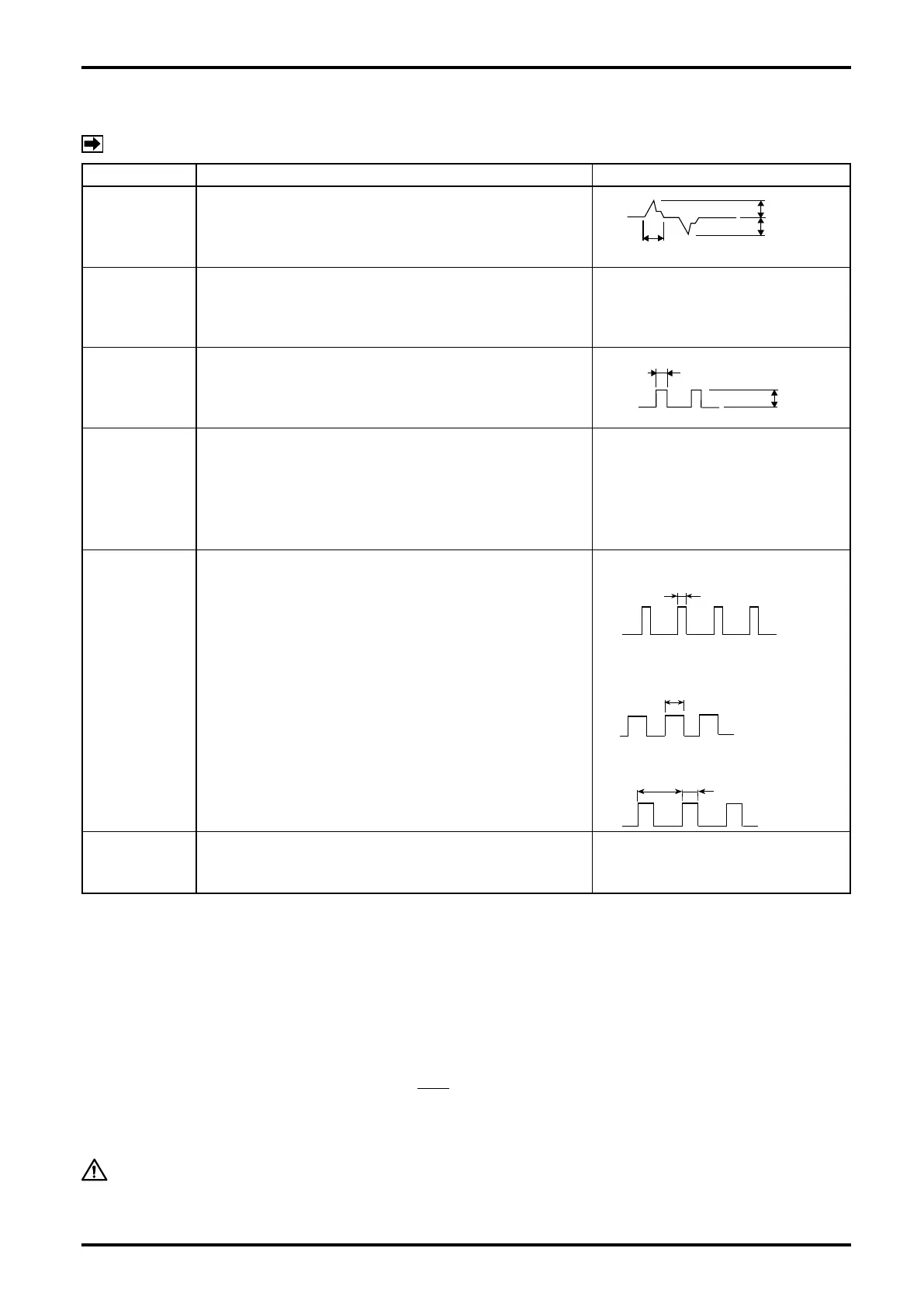
PIN NAME FUNCTION WAVEFORM
FWD
An output of No. 1 amorphous sensor waveform
appears.
REV
An output of No. 2 amorphous sensor waveform
appears. While the owmeter is making forward
revolutions, pulses are produced slightly behind the
FWD pulses.
Same as above.
PLS
A r e c t a n g u l a r w a v e f o r m a f t e r F W D p u l s e
waveshaping appears. Timing remains the same
as that of FWD and its waveform is one before
unfactored output amplication.
IN
Accepts a square-wave pulse train from the pulse
checker (OVAL Model PC2201, for example).
Used for analog full scale adjustment, loop check, or
other servicing. Input mode is Model PC2201's PG30
mode. Also accepts pulses with levels "0": 1V max.
and "1": 7 to 12V min., or open collector.
OUT1
Provides a waveform corresponding to the power
signal which appears across remote output signal
terminals 1 and 2.
(1) Unfactored pulse
(2) Factored pulse
Depends on
"Pulse widt"setting.
(3) Analog output
OUT2
Produces a waveform corresponding to the open
collector output which appears across remote output
terminals 3 and 4.
11.3 About Meter Factor
If it is desired to change meter factors in an instrumental error testing, for example, you may establish a new
meter factor by the following procedure.
Instrumental error testing must be conducted with proper facilities and procedures specied in the Weights and
Measures Law, Japanese Industrial Instruments Federation, JIS standards, or other established standards.
- How to Determine a New Meter Factor
New Meter Factor = (Current meter factor) × (1−
E
100
) (mL/P)
where current meter factor : Stated in the test report or on the tag of the product.
E : Instrumental error determined by the test (% )
CAUTION: The new meter factor should be put on paper for later reference.
T
≒
2 to 10ms
at 0 to FS