B-149-4N-E
6
3. GENERAL DESCRIPTION
Smart Ultra OVAL has been developed to meet the needs of precise owrate measurement. The local direct-
reading total counter is an all-electronic register built around a single-chip CPU. With the latest electronic
technologies used throughout, this versatile register displays accumulated total ow, instantaneous owrate
(digital readout) and provides, by option, a pulse and analog output proportional to the rate of ow.
In this meter, uid ow is detected by sensing with an amorphous sensor the magnetic elds of permanent
magnets embedded in the oval rotors. As a result, high reliability is achieved.
Features
(1) Absence of any mechanically sliding components except for oval rotors contributes to long service life.
(2) Small wetted parts count and pocketless design makes this meter ideally suited for ow measurement of
chemical liquids.
(3) You can monitor accumulated total ow and instantaneous owrate locally on the digital display.
(4) When coupled with a remotely located receiving instrument, output signals can readily and simply be used
for applications including control, adjustment and recording.
(5) IEC explosionproof construction offers increased safety and the design is compact.
(6) A nonvolatile memory, both in the local totalizer type and externally powered type meters, retains
accumulated total in the event of power failure or when de-energized.
NOTE:
With the use over an extended period of time, meter error will deviate more or less from the initial
point. Upon request, we may conduct an instrumental error testing once again and establish a
"new meter factor" in the scaler when your Smart Ultra OVAL is returned to the factory for periodic
inspection or for other reasons.
If you have any request, contact the supplier you purchased the product or our sales ofce.
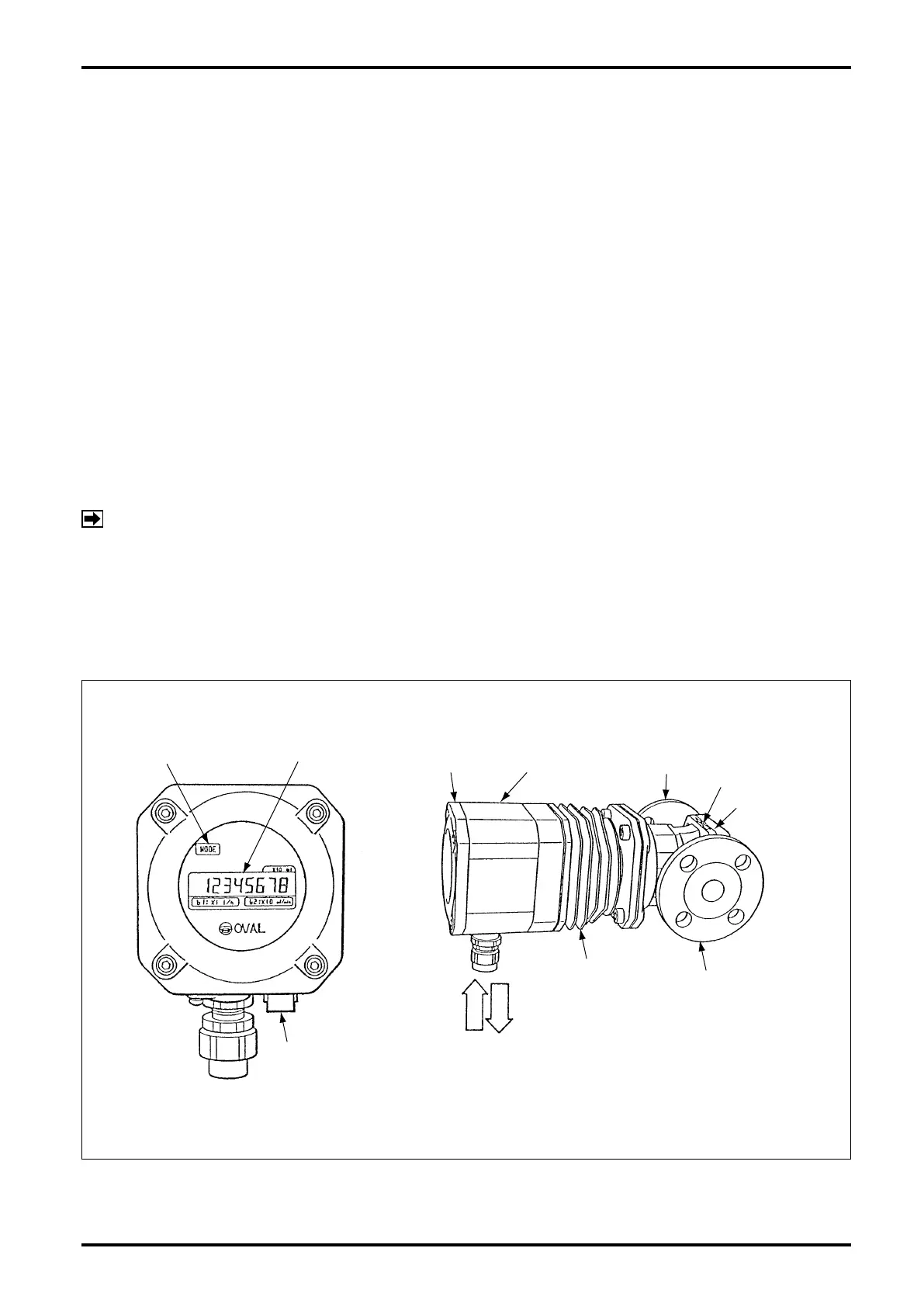
4. PART NAMES
MODE SWITCH LCD COUNTER
FRONT COVER REGISTER
FLOW DIRECTION
REAR COVER
SELECTOR
MAGNET
CONNECTING
FLANGE
METER BODY
COOLING TUBE
(OR HEATING TUBE)
PRESSURETIGHT
PACKING
POWER
SIGNAL
Fig. 4.1