B-149-4N-E
19
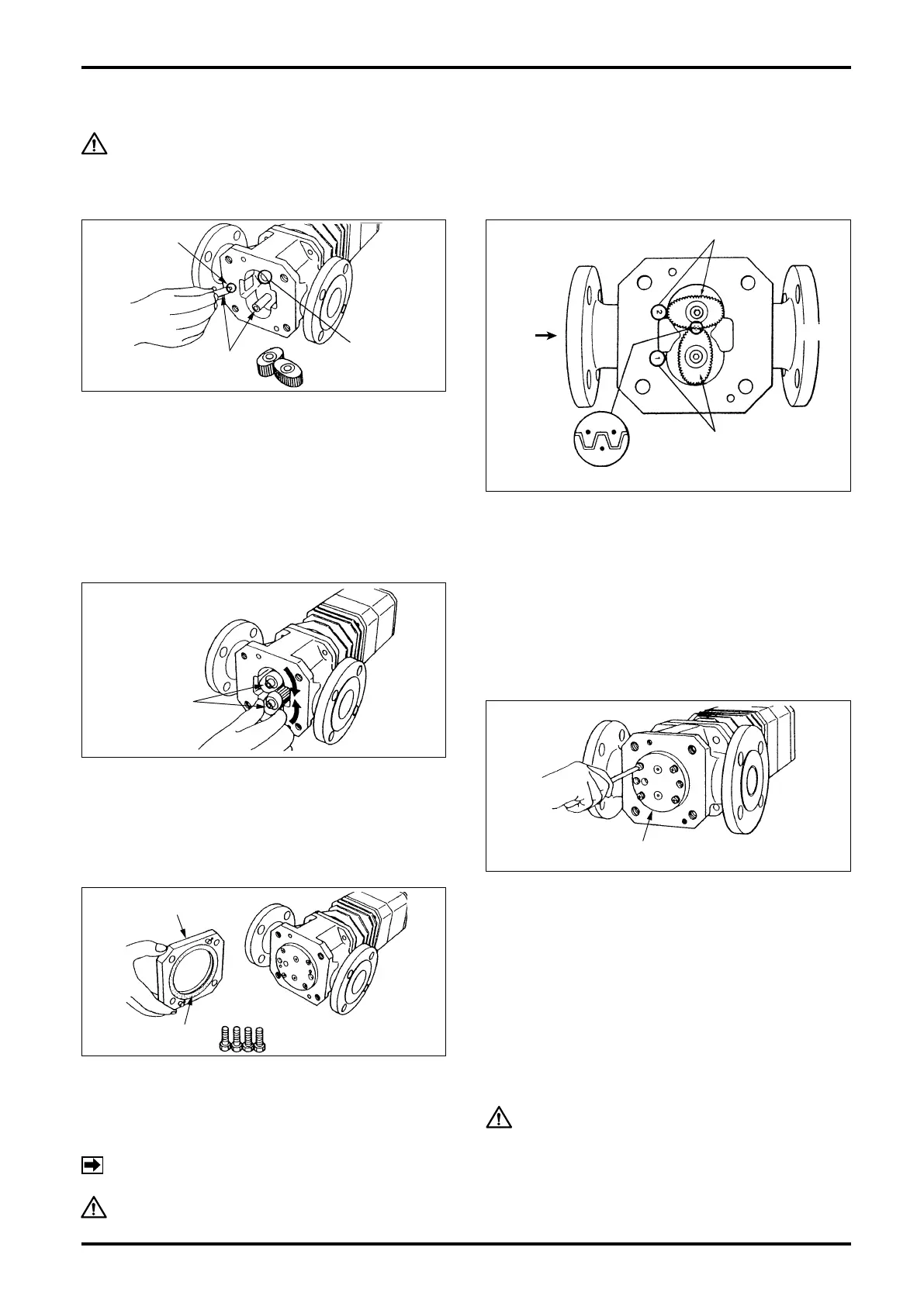
10.4 Sizes 52, 53, 55, 56, 57 Meter Body Assembly Procedure
CAUTION: PRECAUTIONS BEFORE ASSEMBLY
Oval rotors, inner walls of the rotor shafts, inner wall of the measuring chamber, inlet and
outlet ports should be thoroughly washed clean, completely removing dust, grime and other
foreign matter.
NON TURN
PIN
ROTOR
SHAFTS
SHAFT
SOCKET
ROTORS
2ND ROTOR "2" MARKS
1ST ROTOR "1" MARKS
FLOW
IN
OUT
MATCH MARKS
(2) Rotor Installation
Rotor installation is correct if the side where signal
generating magnets are embedded faces the
register (bottom of the measuring chamber) and the
sides with match marks ( • ) ( • • ) faces the rear
cover. Carefully install the rotors with the 1st rotor
(match mark " • ") on the shaft with "1" stamped on
the outside of measuring chamber and the 2nd rotor
(match mark " • •" ) on the shaft with "2" stamped.
Ensure that the match marks are in alignment as
shown in the inset.
(4)
Installing top cover and confirming smooth rotor rotation
With the locating pin of top cover in line with its pin
slot in the meter body and tting the rotor shafts into
their sockets in the top cover, force them against the
meter body until the locating pin ts in its slot in the
meter body without slanting the top cover.
Install top cover fitting bolts and tighten each of
them evenly until the top cover is rmly in contact
with the meter body.
At this point, allowing air or water, make sure to
see that the rotors move freely and that the register
counts in response.
CAUTION
Rotation check should be performed at low rotor
r.p.m. Violent rotor spinning may cause a damage
to meter components, such as bearing seizure.
(5) Rear Cover Installation
Firstly install the gasket on the rear cover. If the
gasket is found damaged, replace it with a new one.
Install rear cover fitting bolts and tighten them
evenly.
NOTE: We suggest to replace the gasket with a
new one at each disassembly.
CAUTION: Since the registers are not compatible each other, do not replace one
register with that of other meter.
(1) Rotor Shaft Installation
The non-turn pin end of each rotor shaft faces the
register (bottom of the measuring chamber). Install
the shafts, pin end first, into their sockets on the
bottom of measuring chamber (bottom of meter
body), forcing downward while turning each of them
with hands until they are rmly installed in position.
(Air in the sockets may resist to be compressed by
the shafts. So good practice is to hold the shafts
pressed down by hand for some time.)
(3) Confirming the Rotor Gear Engagement
Hand rotate the rotors to make sure of correct gear
mesh. At this point, they may be shaky more or less
as the shafts not fixed firmly. Exercise care not to
damage the rotors and inner wall of the measuring
chamber by forcing them to rotate.