B-149-4N-E
7
5. LCD COUNTER DISPLAY
5.1 About "MODE" Switch
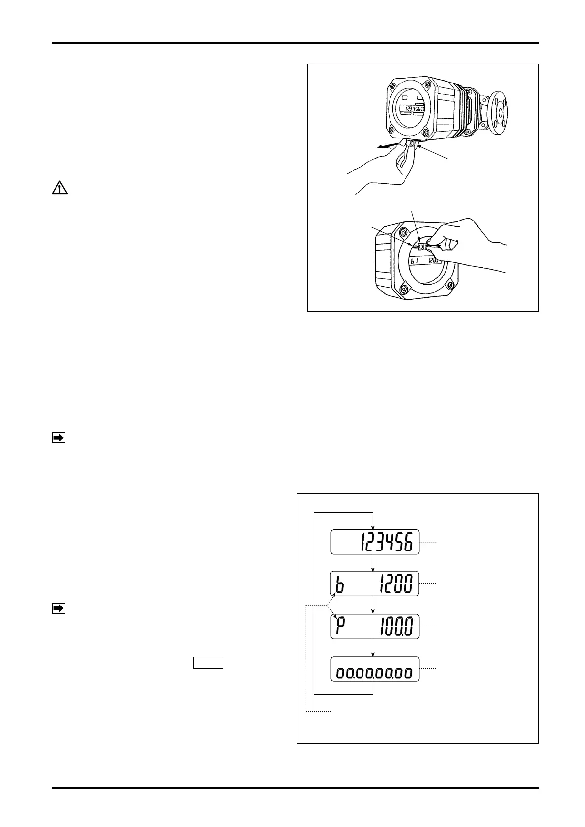
Removing the selector magnet inserted at the
bottom of the register, apply it to the label "MODE"
on the LCD counter face and the display will scroll
forward through the available readings as shown in
Fig. 5.1.
CAUTION
Do not fail to return the selector magnet
to its holder after use lest you will not
lose it. It uses an intensive magnet; never
hold it close to floppy disks or other
magnetic storage media.
5.2 Display Functions
The display can show four different kinds of ow information - total ow, instantaneous actual owrate, percent
instantaneous owrate, and 8-division percent bar graph.
It also shows the following error messages:
Full scale exceeded : ErrorFS
Upper-limit owrate exceeded : ErrorOF
NOTE: Multiple errors will be indicated in priority order below:
ErrorOF > ErrorFS
5.3 Display Mode Selection
Two ways are available to select displays - with a
display select switch inside the register, or through
communications with the Smart Communication Unit
Model EL2310 (or HHC: Model EK10).
If your option is through communications, follow the
instructions outlined in the Smart Communication
Unit EL2310 (or HHC: EK10) instruction manual.
NOTE: Show "Measure" window at "View" menu
on the PC screen.
Selection with display select switch requires access
to the display select switch SW1 by opening
the register cover facing its internal assembly and
pressing this switch (see page 20). The display
scrolls forward through available information each
time you press this switch as shown in Fig. 5.1.
SELECTOR MAGNET
SELECTOR MAGNET
"MODE"
EXAMPLE OF READINGS
MODE SYMBOL
TOTALIZED FLOW
INSTANTANEOUS
ACTUAL FLOWRATE
% INSTANTANEOUS
FLOWRATE
8-DIVISION
BAR GRAPH
Fig. 5.1