B-149-4N-E
20
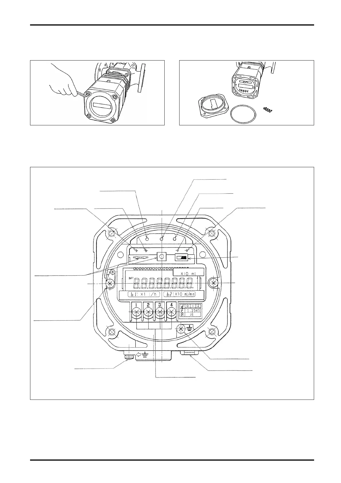
11. REGISTER SWITCH FUNCTIONS AND PARAMETER SETTING
11.1 Switch Names and Functions
(1) Using a hex key, take off four hex socket head
bolts securing the front cover.
O-RING
FRONT
COVER
HEX SOCKET
HEAD BOLTS
(2) Removing the front cover provides access to the
electronics unit.
TP-PIN
OUT 2 PIN
OUT 1 PIN
REV PINFWD PIN
MODE SELECT
SWITCH SW1
0V PICKUP POINT
EXTERNAL GND
TERMINAL
EXT. OUTPUT
TERMINAL
SELECTOR MAGNET
HOLDER
INTERNAL GND
TERMINAL
PARAMETER REWRITE
PROTECT SWITCH
(“ON” TO INHIBIT REWRITE)
IN PIN PLS PIN
Fig. 11.1 Part Names of Electronics Unit