Since there are 8 modulation lanes available, 2 different ways of toggling from the 4 first lanes and the
4 later ones have been implemented.
1- Hold the MOD button and tap any of the rows of the grid. This will automatically show the
modulation lane of the new selected track.
2- Hold any step and the screen will show the modulation value of that step and the selected track.
Turn the first encoder to change the track.
Use the 4th encoder to adjust the modulation value of that step.
MOD LANE ON - OFF
Click the encoder button to turn ON/OFF each lane, preventing it from sending MIDI messages or
internal modulations. When the MOD lane is OFF:
- The selected MIDI parameter will keep its current value.
- The internal modulation will be disabled and the destination will remain untouched
Any twist of the encoder will turn it ON again and jump to the next value.
Press Shift + encoder turn or Shift + encoder click to enter the MOD lane settings.
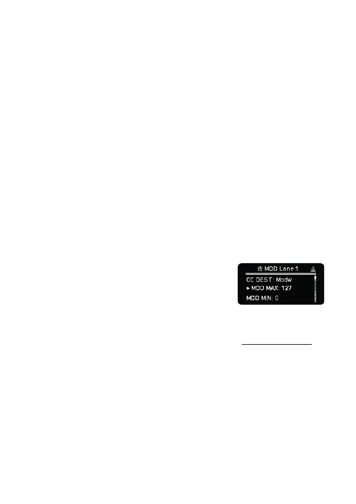
LANE SETTINGS
Press Shift + encoder turn or Shift + encoder click to enter the MOD lane settings. Turn the
encoder of the respective lane to navigate the lane settings menu, click the encoder to enter into a
setting and use back to leave the submenus.
- CC DEST: selects the MIDI parameter (Prog Change,
Aftertouch, Pitch Bend or CC) the modulation lane sends.
- MOD MAX: maximum MOD value that can be set per step for
this lane. From 7 to 127. This is a fast way to select the
maximum modulation value for an internal destination or CC
parameter.
- MOD MIN: minimum MOD value that can be set per step for this lane. From 0 to 120.
- INT DEST 1: Internal parameter destination of this lane. Check the Destination table section for
all the routing options.
- INT AMT 1: % Amount applied After the MOD value. An extra control useful for fine tuning the
range of the internal modulation.
NOTE: As this version of the firmware, the Amount is an absolute value. Depending on the destination
parameter, the MOD Amount required may be as little as 1 - 2 units - Octave, Arp Division, etc. - or up
to 100 for other parameters like Velocity, Gate, Trigger probability.
- INT OFF 1: Offset to the MOD lane values before applying the internal modulation. Use it to get
negative or bipolar modulation values.
- INT DEST 2: Defines the 2nd internal destination.
- INT AMT 2: Amount of the 2nd internal destination.
- INT OFF 2: Offset of the 2nd internal destination.