steel enclosure)
Figure 3: XMT1000 enclosure clearances (ref. dwg. 712-2164)
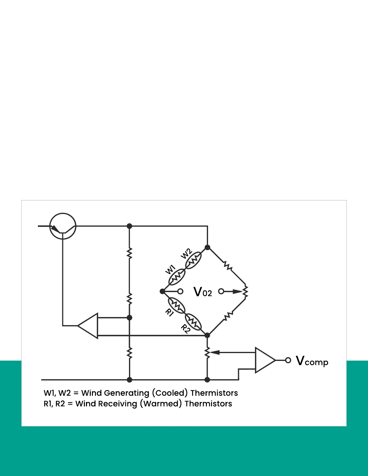
Figure 3 below shows how the two thermistor pairs are
connected in series in an electronic bridge circuit. The
bridge circuit becomes unbalanced as the electrical
resistance of the thermistors changes with temperature.
This circuit imbalance causes a voltage drop, which is
proportional to the oxygen concentration in the gas being
measured, to appear across the bridge circuit.
As the background gases that comprise the balance of an
oxygen-containing gas mixture change, the magnetic and
thermal properties of the gas mixture also change. This
affects the accuracy and response of any paramagnetic
oxygen analyzer. To compensate for such variations, the
XMO2 has a unique “bridge-within-a-bridge” design.
The oxygen measuring bridge circuit described on the
previous page is itself one arm of another compensation
bridge circuit that maintains the oxygen bridge at a
constant temperature as background gas composition
changes. The electrical power change necessary to keep
the oxygen bridge at constant temperature is a function of
the thermal properties of the background gas. Therefore,
this power fluctuation provides a signal that is related to
the thermal conductivity of the background gas. That signal
is then used to reduce the effects of the background gas
variation on the oxygen span point measurement.
In addition to maintaining a constant oxygen bridge
temperature, the XMO2 microprocessor compensates
for any zero point shift in the oxygen bridge circuit output
caused by background gas changes.
Finally, the bridge circuit voltage is further adjusted
for variations in background gas composition and/or
atmospheric pressure by internal, microprocessor-based
compensation algorithms. The compensated signal is then
amplified and converted to a 4-20 mA analog output that
is proportional to the concentration of oxygen in the gas
mixture.
3