6. If you are installing the second cable entry device, do so
in accordance with the manufacturer’s instructions.
Note: If installation of the cable entry device is only partially
complete, Panametrics recommends tagging the device to
ensure the safety of subsequent users.
a. Thread the cable gland entry body into the
remaining XMO2 port.
b. Route the 3-wire RS232 cable through the cable
gland as shown in Figure 89 on page 70.
c. After terminating the shield as shown, assemble the
three gland pieces together and tighten the gland
to secure the cable and the shield.
IMPORTANT:
The cable shield must be terminated in the cable gland as
shown in Figure 89 on page 70.
7. Unplug the TB2 connector by pulling it straight out of
its socket, and loosen the terminal screws on the TB2
connector.
8. Connect the RS232 serial port leads:
a. Insert the 3-wire cable RX (red) lead into pin TB2-1
and tighten the screw.
b. Insert the 3-wire cable TX (white) lead into pin TB2-2
and tighten the screw.
c. Insert the 3-wire cable GND (green) lead into pin
TB2-3 and tighten the screw.
9. Carefully plug the TB2 connector into its socket.
10. Reinstall the cover on the XMO2.
11. Connect the other ends of the cables to the 24 VDC
power supply, the 4-20 mA input of the display device,
and the serial port of the computer or terminal (see the
instruction manuals for those devices for details).
E.4 Wiring the signal connections
for the explosion/flameproof version
Refer to Figure 88 on page 69, and complete the following
steps to make the proper wiring connections:
WARNING!
Cable entries of an approved flameproof
design are required. These must be installed
according to the manufacturer’s instructions.
The choice of a cable entry device may limit
the overall installation category achieved.
1. Install the first cable entry device in accordance with
the manufacturer’s instructions.
Note: If installation of the cable entry device is only partially
complete, Panametrics recommends tagging the device to
ensure the safety of subsequent users.
a. Remove the tab “Remove Before Installation”.
b. Thread the cable gland entry body into the XMO2
port closest to the terminal blocks.
c. Route the 4-wire power/analog output cable and its
ground lug through the cable gland.
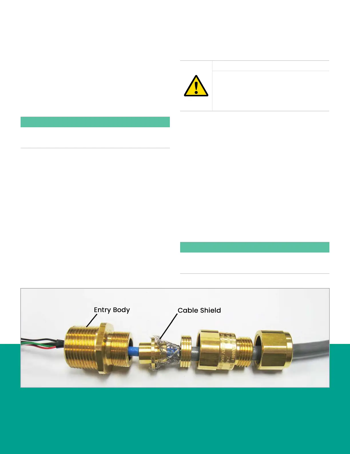
d. Fray the braided shield and spread evenly around
the cone as shown in Figure 90 below. Compress
the ring to lock the shield.
e. After terminating the shield as shown, assemble
the gland pieces together and tighten the gland to
secure the cable and the shield.
IMPORTANT:
The cable shield must be terminated in the cable gland as
shown in Figure 90 below.
Figure 90: Proper cable gland assembly (Panametrics p/n 419-217)
71