3.10.3 Span gas pushbutton calibration
To perform a span gas pushbutton field calibration,
complete the following steps:
1. Using the sample system controls, stop the flow of
sample gas to the XMO2 inlet port and initiate a flow of
the same span gas specified on the XMO2 Calibration
Sheet. Establish the same flow rate and pressure
conditions used for the sample gas, and allow the span
gas to flow through the XMO2 for at least three minutes.
2. Using Figure 11 on page 17 as a guide, locate the Zero/
Span Selector (Switch S1). Set the Zero/Span Selector
(Switch S1) to position “3” (“Span”).
3. Using Figure 11 on page 17 as a guide, locate the
Calibration Pushbutton (Switch S3). Depress the
Calibration Pushbutton and hold it down for 20 seconds.
During this time, the green light below the Calibration
Pushbutton will go out.
4. When the Calibration Pushbutton is released, the
green light will come back on and the XMO2 has been
recalibrated.
You may now return the XMO2 to normal operation by using
the sample system controls to stop the span gas flow and
restart the flow of sample gas.
3.11 IDM digital communication
calibration
At the initial startup of the XMO2, IDM Digital Communication
Calibration is the second method available for field
verification/calibration of the 4-20 mA analog output.
Note: IDM can also be used to change the 4-20 mA analog
output range. See the next section for details.
To prepare for this calibration method, refer to Figure 10 on
page 17 and perform the following preliminary steps:
1. Make sure that the RS232 digital output of the XMO2
has been connected to a computer or terminal in
accordance with the instructions given in Chapter 2,
Installation.
2. Loosen the set screw that locks the XMO2 cover in place,
and unscrew the cover.
IMPORTANT:
Remember to replace the cover after the calibration has
been completed.
3. Turn the computer or terminal on and launch IDM.
Note: Be sure you have properly installed Instrument Data
Manager on your PC before attempting to program the
XMO2.
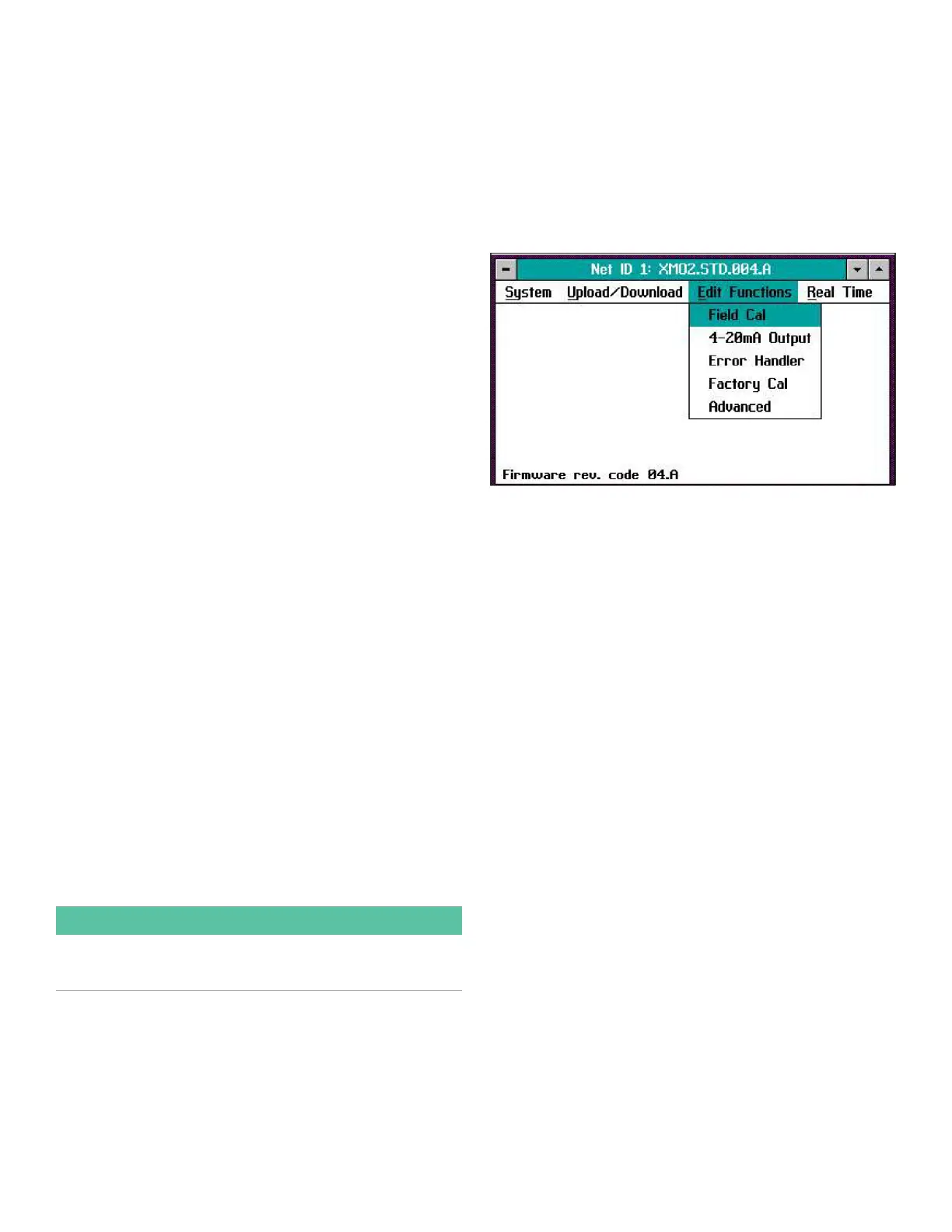
3.12 The edit functions menu
To access the XMO2 calibration, pull down the Edit Functions
menu from the Instrument window. This menu consists of the
five commands displayed in Figure 12 below. To access any
of the commands, simply select it from the menu.
Note: As a programming aid, the relevant portions of the Edit
Functions menu have been mapped in Figure 75 on page 62
and Figure 76 on page 63.
Figure 12: Edit functions menu
The following three buttons appear at the right of all menu
windows (see Figure 13 on page 20):
• Previous Item - returns you to the previous window
(either the command menu or the previous parameter
entered).
• Next Item/Enter - confirms the selection or data entered,
and either opens the next window or returns you to the
command menu (depending on your position in the
program).
• Exit Page - returns you to the command menu.
19