105
[Connections and Settings in Internal Velocity Control Mode]
Connections and
Settings in Internal
Velocity Control Mode
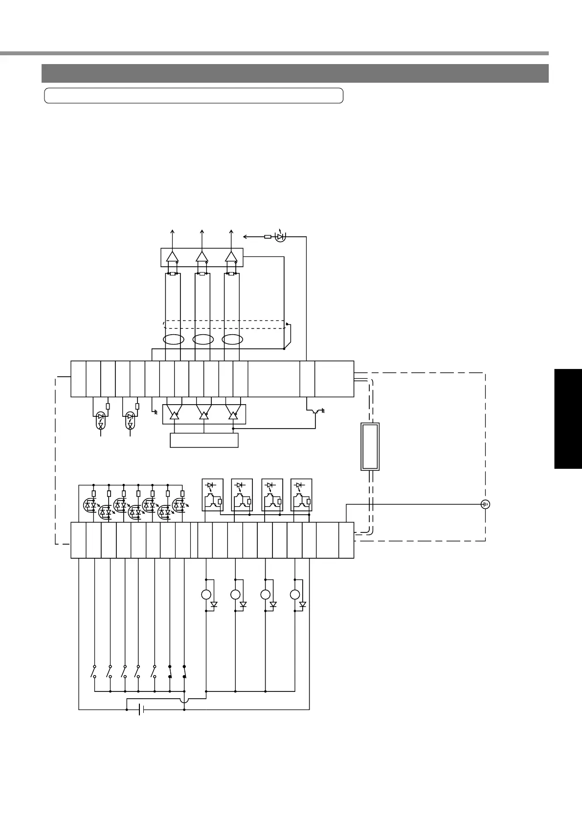
* Default setup of CWL and CCW inputs is “invalid”
with Pr04 overtravel inhibit parameter (Pr04=1).
The figure shows an example of wiring when Pr04
is valid (Pr04=0).
1
4.7kΩ
COM+
PULS2
SIGN1
SIGN2
OA+
OA
-
OB+
OB
-
OZ+
OZ
-
CZ
22
23
24
25
15
GND
14
16
17
20
21
18
19
PULS1
SRV-ON
A-CLR
INTSPD2
ZEROSPD
INTSPD1
CWL
CCWL
ALM
COIN
BRKOFF
WARN
COM
-
CN X5
FG
3
4
2
5
6
7
8
9
10
11
12
13
26
Alarm clear
Internal command
speed selection 2
Divider
Internal command
speed selection 1
*
CW overtravel inhibit
A-phase output
B-phase output
Z-phase output
Z-phase output (open collector)
*CCW overtravel inhibit
Servo alarm
At-speed
Mechanical brake
release
Alarm
(Pr09)
V
DC
12~24V
Servo-ON
Speed zero clamp
220Ω
220Ω
330Ω
330Ω
330Ω
<Remarks>
Example of Wiring to Connector CN X5
Example of Wiring in Internal Velocity Control Mode
Wiring to Connector CN X5
Buy: www.ValinOnline.com | Phone 844-385-3099 | Email: CustomerService@valin.com