68
Interface Circuit
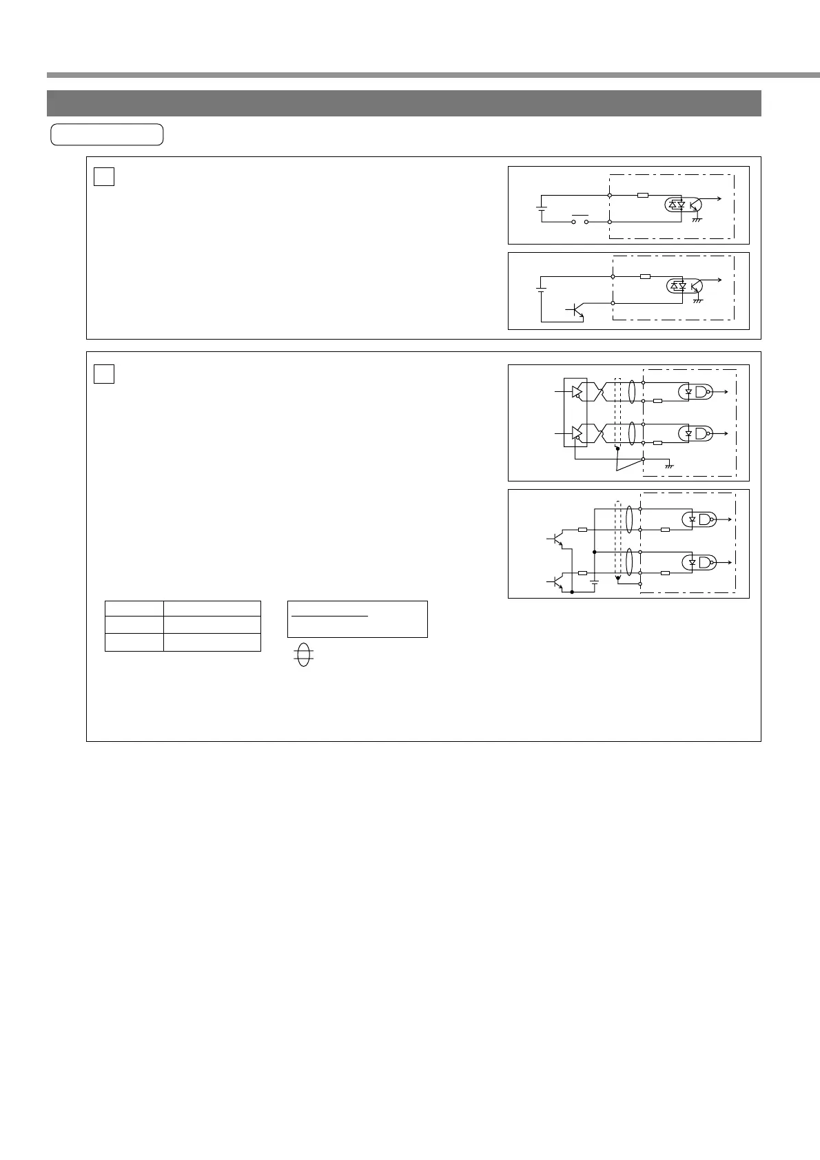
Input Circuit
Command Pulse Input Circuit
(1) Line Driver I/F
• This signal transmission method is less susceptible to
effects of noise. We recommend this method to improve
reliability of signal transmission.
(2) Open Collector I/F
• The method uses control power supply (VDC) external to the
driver.
• This requires a current-limiting resistor (R) that relies on VDC.
• Be sure to connect specified resistor (R).
PI
Connection with Sequence Input Signal
• Connect to a contact of switch and relay, or a transistor of an
open collector output.
• When you plan to use a contact input, use switch and relay
for minute electric current so as to avoid poor contact.
• In order to secure appropriate level of primary current of the
photo coupler, set lower limit voltage of the power supply (12
to 24 V) 11.4V or more.
SI
VDC Specification of R
12V 1kΩ 1/2W
24V 2kΩ 1/2W
12~24V
1
COM+4.7kΩ
SRV-ON, etc.
Relay
V
DC
1
COM+4.7kΩ
12~24V
SRV-ON, etc.
V
DC
PULS1
PULS2
SIGN1
GND
SIGN2
220Ω
220Ω
V
DC
R
R
22
23
24
25
14
(1)
(2)
This represents a twisted pair cable.
Maximum Input Voltage DC24V
Rated Current: 10mA
Wiring to Connector CN X5
.
=.10mA
VDC—1.5
R+220
When the connection method is inversed if you use the CW pulse row + CCW pulse row method as
pulse input form, pulses do not count and the motor does not rotate.
Connect so that a photo coupler in the driver on the side on which pulse input is not done turns OFF.
Item Equivalent to AM26LS31
22
PULS1
PULS2
SIGN1
SIGN2
GND
220Ω
220Ω
23
24
25
14
Buy: www.ValinOnline.com | Phone 844-385-3099 | Email: CustomerService@valin.com