107
[Connections and Settings in Internal Velocity Control Mode]
Connections and
Settings in Internal
Velocity Control Mode
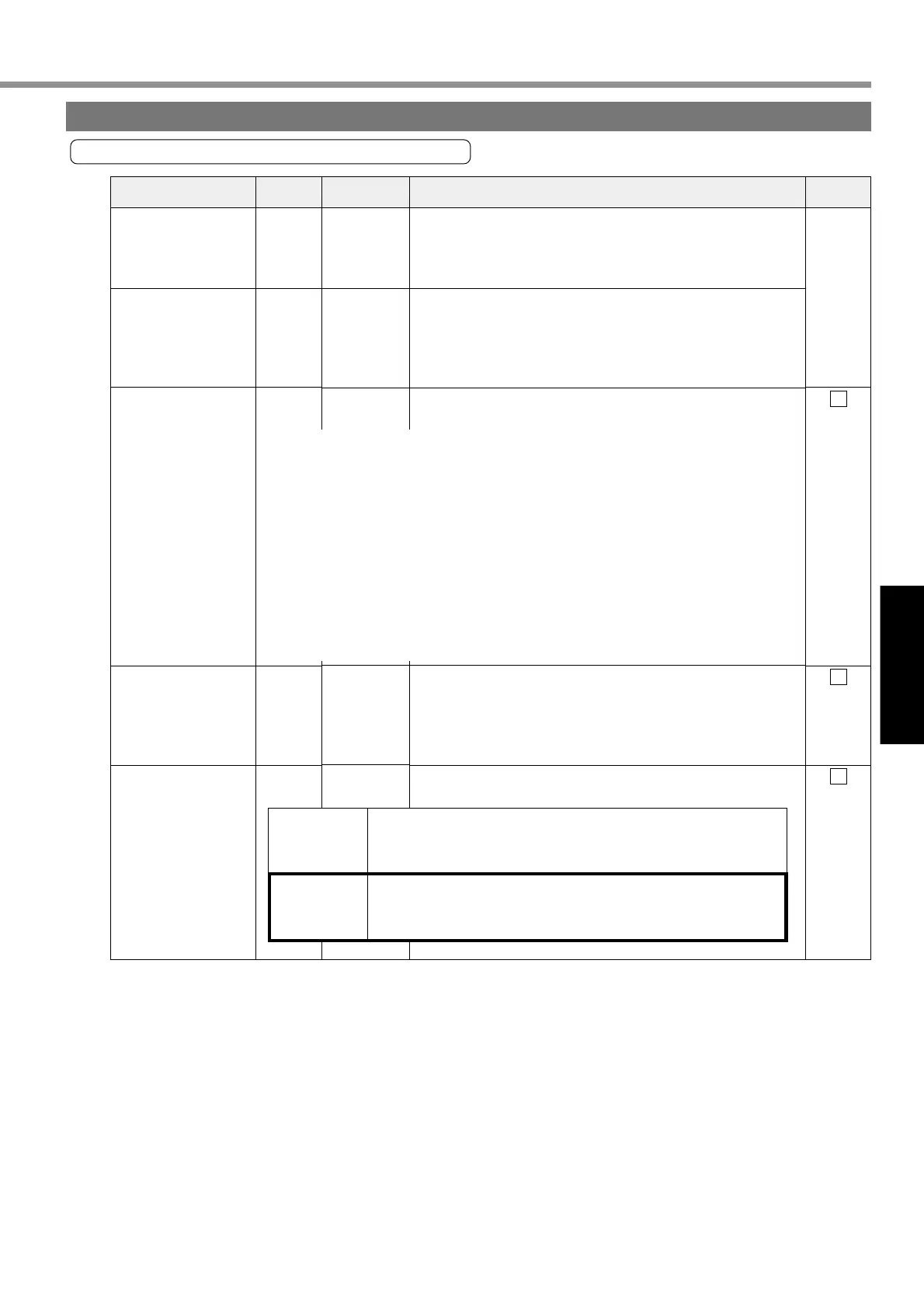
Signal Name
Control Signal Power
Supply Input (+)
Control Signal Power
Supply Input (—)
Servo-ON input
Alarm Clear Input
Deviation Counter
Clear/Internal
Command Speed
Selection 2 Input
• Connect positive (+) pole of external DC power supply (12 to
24V).
• Total supply voltage should range from 12V ± 5% to 24V ± 5%.
• Connect negative (-) pole of external DC power supply (12 to
24V).
• The voltage source capacity varies depending on configuration
of input/output circuits to be used. We recommend 0.5A or
greater.
• When this signal is connected to COM-, the driver will be
enabled (Servo-ON) (motor energized).
• If this signal is connected to COM- for 120 ms or longer, it will
clear alarm status.
• There are some alarms that this signal cannot release.
For details, refer to “Protective Functions” on Page 144 of
Edition of When You Have Trouble.
The control mode changes functions.
1
13
2
3
4
——
SI
Page 106
SI
Page 106
SI
Page 106
Pin No. Symbol Function I/F Circuit
Input Signal and Pin No. of Connector CN X5
Input signals (common) and their functions
COM+
COM–
SRV-ON
A-CLR
CL/
INTSPD2
<Cautions>
1. The signal will become valid about 2 seconds after power-ON.
(See the timing chart.)
2. Don’t use Servo ON/OFF signal to drive/stop the motor. Refer to “Dynamic Brake”
on Page 36 of Preparation edition.
• Take the time of 100 ms or longer before entering a command on speed, pulse, etc.,
after transition to Servo-ON.
• When you open the connection with COM-, the driver will be disabled (Servo-OFF)
and the current flow to the motor will be cut off.
• You can select dynamic brake operation during Servo-OFF and clear operation of
the deviation counter by using Pr69 (sequence during Servo-OFF).
Position
Control
Internal
Velocity
Control
• Input of this signal is to clear the deviation counter.
• When the signal is connected to COM- for 2 ms or longer, it will
clear the deviation counter.
• With input of internal command speed selection 2 (INTSPD2),
four-speed can be set in combination with INTSPD1 input.
• For details on settings of control mode, refer to Page 117.
Buy: www.ValinOnline.com | Phone 844-385-3099 | Email: CustomerService@valin.com