29
9 Service Position
Note: For description of the disassembly procedures, refer Section 8 of the Service Manual.
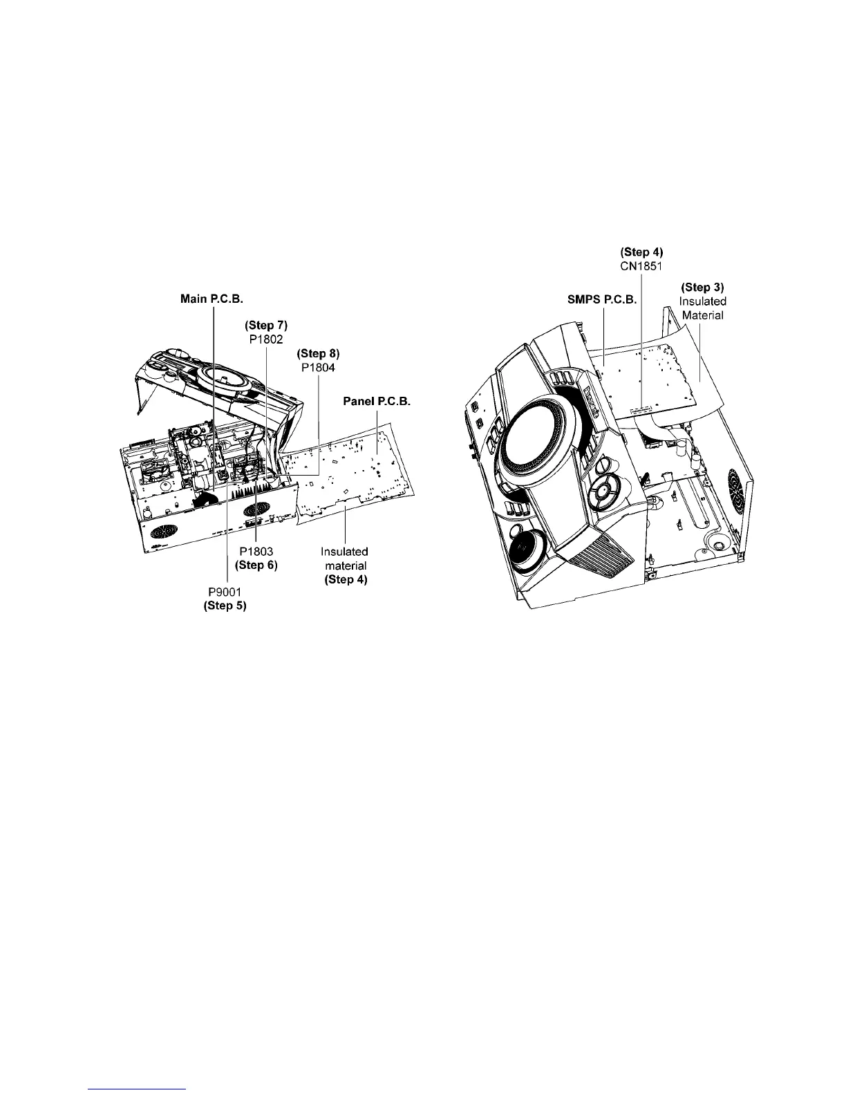
9.1. Checking of Panel P.C.B.
Step 1 Remove Top Cabinet.
Step 2 Remove Front Panel Unit.
Step 3 Remove Panel P.C.B..
Step 4 Place Panel P.C.B. on the insulated material.
Step 5 Attach 12P Cable at connector (P9001) on Main P.C.B..
Step 6 Attach 9P Cable at connector (P1803) on Main P.C.B..
Step 7 Attach 30P FFC at connector (P1802) on Main P.C.B..
Step 8 Attach 12P FFC at connector (P1804) on Main P.C.B..
Step 9 Panel P.C.B. can be checked as diagram shown.
9.2. Checking of SMPS P.C.B.
Step 1 Remove Top Cabinet.
Step 2 Remove SMPS P.C.B..
Step 3 Place SMPS P.C.B. on the insulated material.
Step 4 Attach 13P Cable at connector (CN1851) on SMPS
P. C .B ..
Step 5 SMPS P.C.B. can be checked as diagram shown.