41
12 Schematic Diagram
12.1. Schematic Diagram Notes
• This schematic diagram may be modified at any time
with the development of new technology.
Notes:
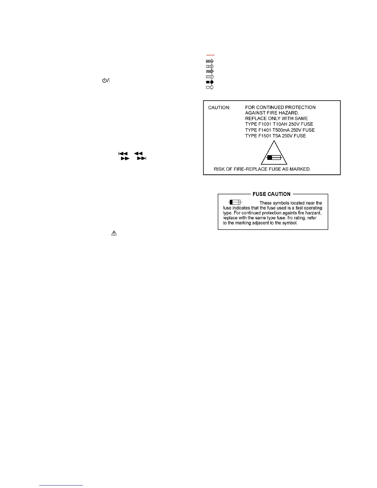
• Important safety notice:
Components identified by mark have special characteris-
tics important for safety.
Furthermore, special parts which have purposes of fire-retar-
dant (resistors), high quality sound (capacitors), low-noise
(resistors), etc are used.
When replacing any of components, be sure to use only
manufacturer’s specified parts shown in the parts list.
• Resistor
Unit of resistance is OHM [] (K=1,000, M=1,000,000).
• Capacitor
Unit of capacitance is F, unless otherwise noted. F=Farads,
pF=pico-Farad.
• Coil
Unit of inductance is H, unless otherwise noted.
•
*
REF IS FOR INDICATION ONLY.
• Voltage and signal line
S6201:
Power ( ) switch.
S6202: Open/Close switch.
S6203: Tune mode switch.
S6204: Bluetooth/Pairing switch.
S6205: Memory/USB switch.
S6206: DJ1 switch.
S6207: DJ2 switch.
S6208: DJ3 switch.
S6209: Illumination switch.
S6210: Effect/Sampler switch.
S6211: Jukebox switch.
S6212: DJ6 switch.
S6213: DJ5 switch.
S6214: DJ4 switch.
S6215: Rewind/Skip ( / ) switch.
S6216:
Forward/Skip ( / ) switch.
S6217: Album/Track switch.
S6218: Memory/Record switch.
S6219: USB Rec switch.
S6220: Latin/EQ switch.
S6221: CD/Radio/Aux switch.
S6222: Play/Pause switch.
S6223: D.Bass switch.
S7201: Reset switch.
VR1400: Mic volume Jog.
VR6201: Multi Control Jog.
VR6202: Volume Jog.
: +B signal line
: CD signal line
: Mic/Aux/Tuner signal line
: Audio signal line
: USB signal line
: AM signal line
: FM signal line